Themal Type Flow Rate Measurement Apparatus
a flow rate measurement and flow rate technology, applied in the direction of machines/engines, electrical control, instruments, etc., can solve problems such as errors in output signals, and achieve the effects of improving driving performance and productivity, reducing variation in correction, and improving accuracy of flow rate measurements during pulsation or respons
- Summary
- Abstract
- Description
- Claims
- Application Information
AI Technical Summary
Benefits of technology
Problems solved by technology
Method used
Image
Examples
first embodiment
[0109] as described above, the following advantages are provided: pulsation errors in the sensor output of the thermal type flow rate meter can be decreased; and restrictions (restriction factors such as throttle opening and engine speed) for the user on using the present sensor are reduced. Also, it is possible to realize a flow rate meter in which variation in response delay correction (response delay rectification) is reduced and improving the driving performance and productivity of motor vehicles can easily be achieved.
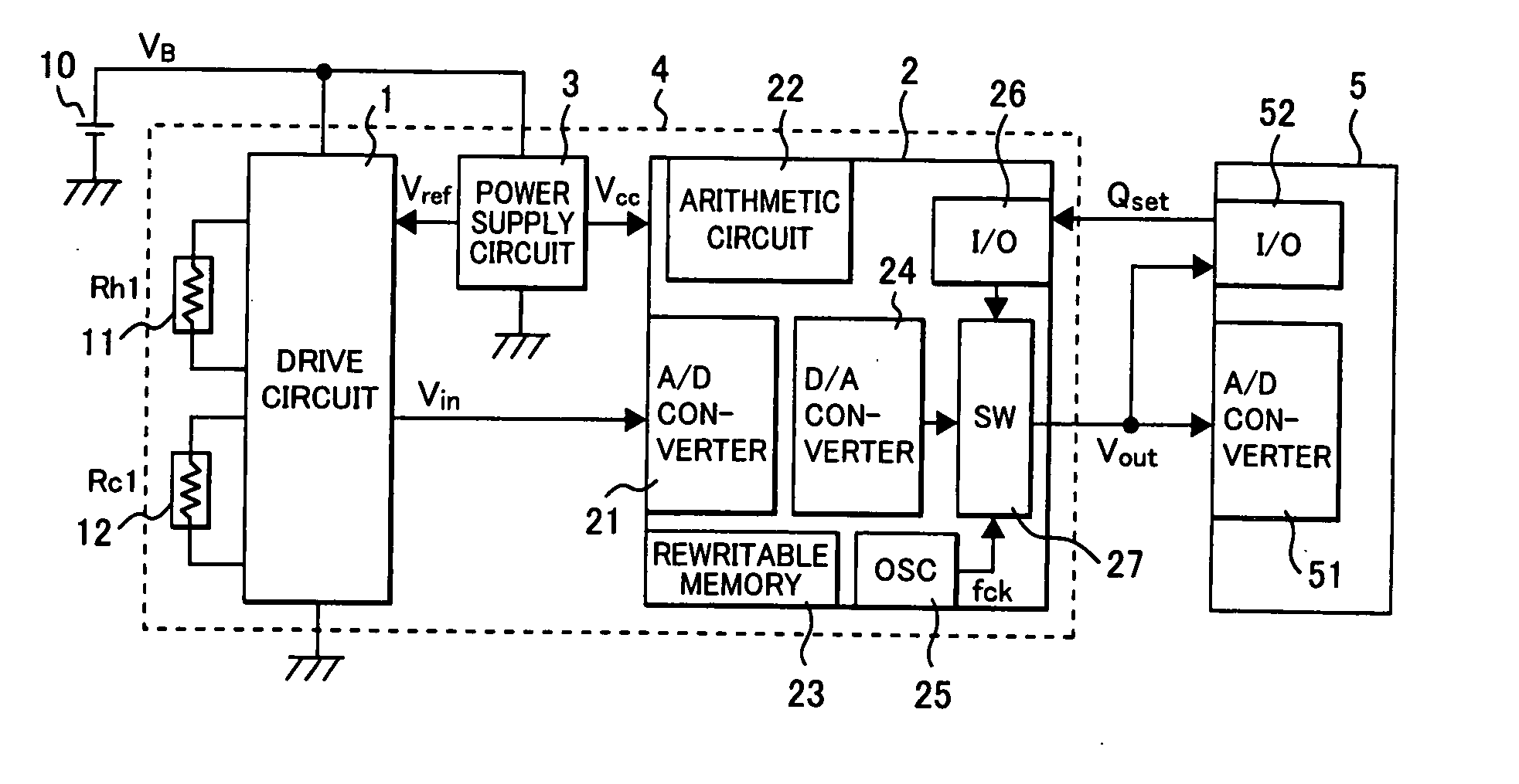
[0110] Next, a second embodiment of the present invention is described, referring to FIG. 12. This is an example of a flow rate meter using a frequency signal as an output signal fout (corresponding to Vout in the first embodiment) of the sensor 4.
second embodiment
[0111] Difference from the foregoing embodiment is that a digital-frequency converter (D / F converter) 28 is used instead of the D / A converter 24 to output a signal and the second embodiment has a feature that signal superimposition is easy to do, as signals in pulses are handled. The controller 5 is provided with a timer 53 for frequency counting and is configured such that a reference signal Tref such as a crank angle of the engine can be taken in to the controller. The response of an output signal fout from the sensor can be selected and switching to a reference clock signal fck can be performed optionally, as is the case in the foregoing embodiment.
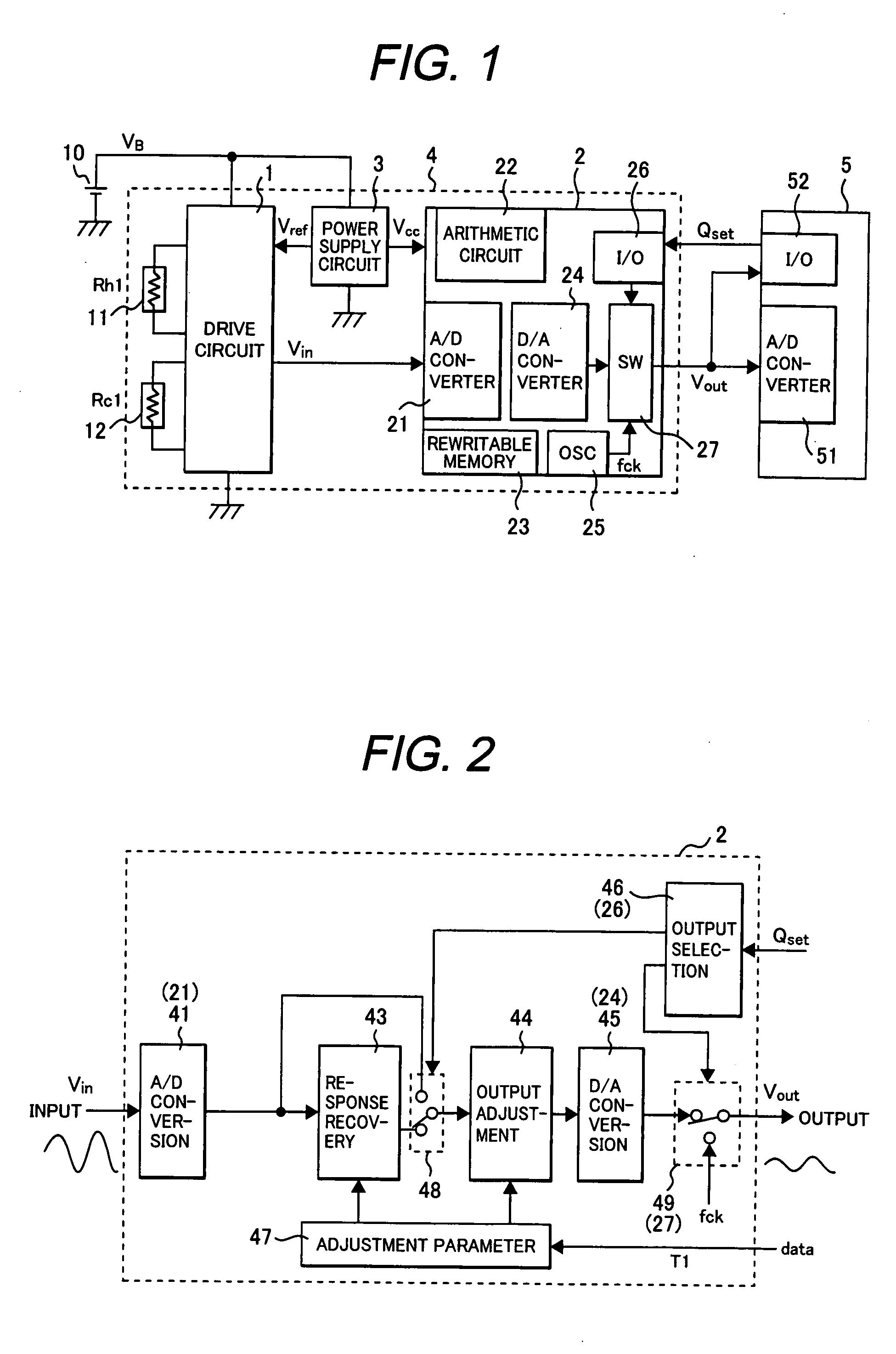
[0112] A flow of detailed arithmetic processing is explained, referring to FIG. 13. The digital processing device 2 takes in an output Vin of the sensor 1, converts the analog input signal into a digital value by analog-digital conversion processing 41, optionally performs response recovery processing 43 by digital means, and performs ...
third embodiment
[0125]FIG. 15 illustrates details of arithmetic processing of the digital processing device 2 in the flow rate sensor 4 in the invention.
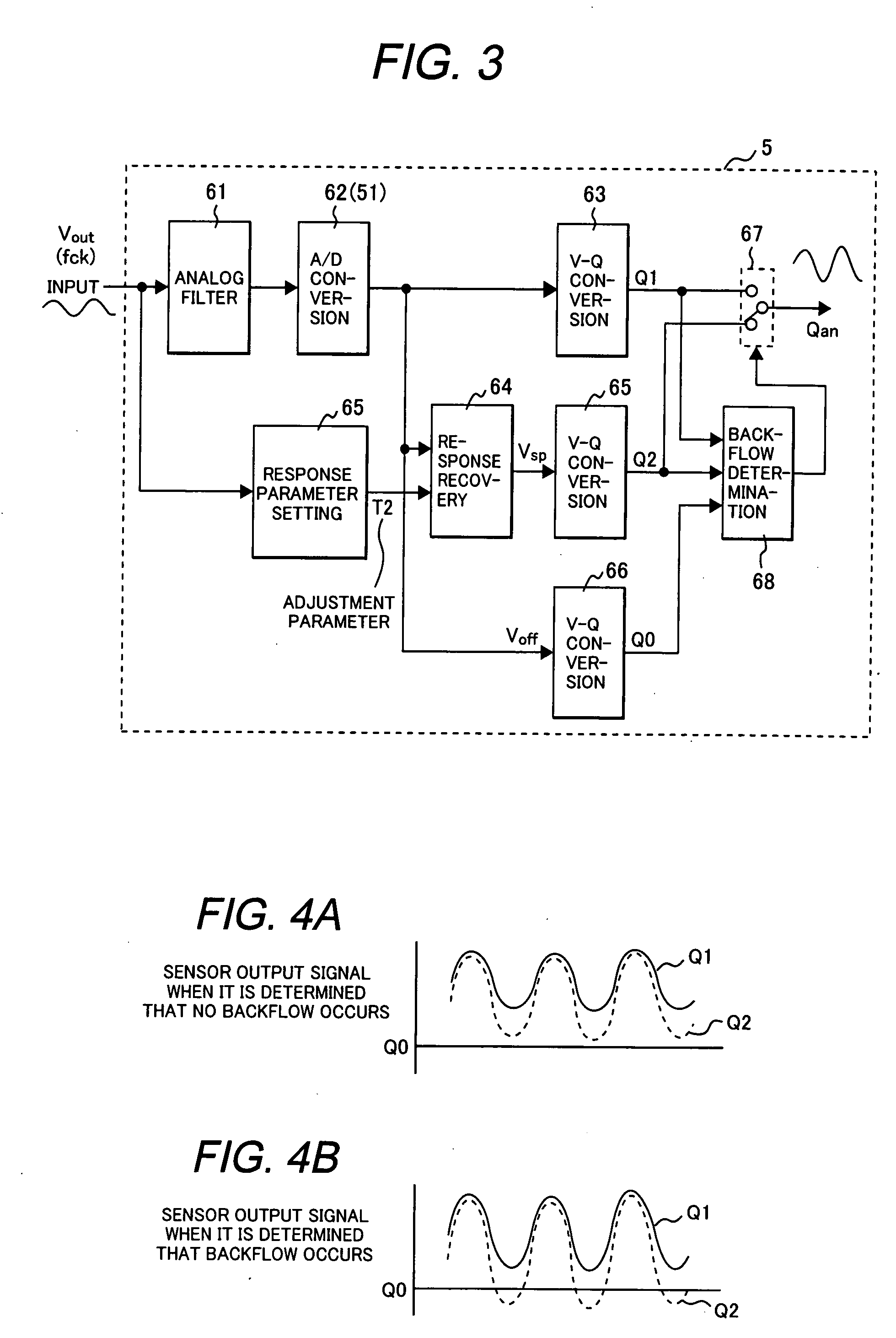
[0126] In the third embodiment, the flow rate sensor 4 itself (digital processing device 2) determines whether a backflow occurs. The digital processing device 2 takes in an output Vin of the drive circuit 1 and converts it into a digital value by analog-digital conversion 41. The converted digital value is processed as Vin1 directly by output adjustment processing 44 through a soft switch (selector switch) 48 or processed by response recovery processing 43 by digital means (a signal having response recovery is referred to as Vin2) and, then, processed by the output adjustment processing 44.
[0127] The signal processed by the output adjustment processing 44 is converted into an analog signal by a digital-analog converter 45 and output.
[0128] In this embodiment, backflow determination processing 47 for selecting whether or not to execute the respon...
PUM
 Abstract
Description
Claims
Application Information
 - R&D
- Intellectual Property
- Life Sciences
- Materials
- Tech Scout
- Unparalleled Data Quality
- Higher Quality Content
- 60% Fewer Hallucinations
Browse by: Latest US Patents, China's latest patents, Technical Efficacy Thesaurus, Application Domain, Technology Topic, Popular Technical Reports.
© 2025 PatSnap. All rights reserved.Legal|Privacy policy|Modern Slavery Act Transparency Statement|Sitemap|About US| Contact US: help@patsnap.com


