Method For Dispersing Nanoparticles and Methods for Producing Nanoparticle Thin Films By Using The Same

a nanoparticle and thin film technology, applied in the field of nanoparticle dispersing, can solve the problems of nanoparticle defects, easy dispersal, and destruction of nanoparticles, and achieve the effects of avoiding the formation of defects of nanoparticles

Inactive Publication Date: 2008-05-01
SAMSUNG ELECTRONICS CO LTD +1
View PDF9 Cites 31 Cited by
  • Summary
  • Abstract
  • Description
  • Claims
  • Application Information

AI Technical Summary

Benefits of technology

[0011]In one embodiment, the present invention provides a method for dispersing nanoparticles by modifying the surface of nanoparticles to allow the nanoparticles to be charged and adjusting the pH of an aqueous dispersion of the charged nanoparticles to control the number density of the nanoparticles arranged upon the surface of a substrate.

Problems solved by technology

However, since nanoparticles have a strong tendency toward aggregation between the individual nanoparticles, they do disperse easily.
However, when sonication is applied to separate nanoparticle aggregates for a long period of time, high ultrasonic energy used during the sonication results in the destruction of nanoparticles or causes the occurrence of defects of nanoparticles.
If the reaction time is shortened in order to prevent the occurrence of defects, some reactants remain unreacted and the yield becomes low.
In addition, when aggregated particles are separated from each other using a column or a filter, a high water pressure has to be applied to the filter for a long time and the nanoparticles are adsorbed to the filter, resulting in a loss of the nanoparticles.
Accordingly, these separation processes are unsuitable for mass production of nanoparticles without aggregation.
However, since this technique utilizes weak van der Waals interactions between individual particles or between particles and the substrate, the transfer ratio, which is defined as the percentage of the number of the particles transferred to the substrate, is usually never higher than 1.
Accordingly, the Langmuir-Blodgett technique is not suitable for the formation of uniform monolayers in large areas.
However, this technique causes the aggregation of nanoparticles in its practical use, which results in the occurrence of defects and low degree of completeness.
However, these techniques have problems in that a uniform monolayer having a density as high as 1011 nanoparticles / cm2 cannot be formed in a large area.

Method used


Image

  • Method For Dispersing Nanoparticles and Methods for Producing Nanoparticle Thin Films By Using The Same
  • Method For Dispersing Nanoparticles and Methods for Producing Nanoparticle Thin Films By Using The Same
  • Method For Dispersing Nanoparticles and Methods for Producing Nanoparticle Thin Films By Using The Same

Examples


example 1

Surface Modification and Dispersion of Nanoparticles

[0059]1 mL of mercaptoacetic acid was slowly added dropwise to 10 mL of a dispersion of palladium (Pd) nanoparticles (0.1 wt %) in toluene under a nitrogen atmosphere. The mixture was reacted while stirring rapidly for 4 hours. The reaction temperature was maintained at 100° C. to modify the surface of the Pd nanoparticles. As a result of the reaction, the surface of the Pd nanoparticles was negatively charged. The Pd nanoparticles were not readily dispersed in the toluene as the reaction proceeded. After completion of the reaction, the reaction mixture was centrifuged at 9,000 rpm for 5 minutes to separate a precipitate of the nanoparticles.

[0060]The precipitated nanoparticles were re-dispersed in chloroform by sonication and centrifuged at 9,000 rpm for 5 minutes to wash the precipitated nanoparticles. The series of re-dispersion and centrifugation was repeated five times or more to remove the unreacted mercaptoacetic acid. The w...

example 2

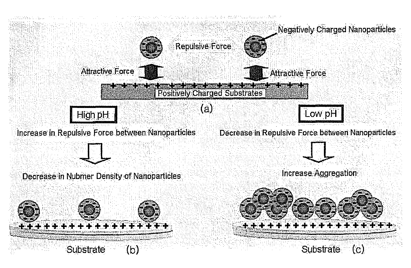
pH Adjustment of Nanoparticle Dispersions

[0062]The Pd nanoparticles surface-modified with the mercaptoacetic acid, which were prepared in Example 1, were dispersed in Tris buffer solutions having different pH values of 7.0, 7.4, 7.8, 8.2, 8.6 and 9.0. The respective pH-controlled Tris buffer solutions were prepared by adding appropriate amounts of a 0.1 M HCl solution to 0.1 M Tris buffer solutions. The pH values of the pH-controlled Tris buffers were determined using a pH meter.

example 3

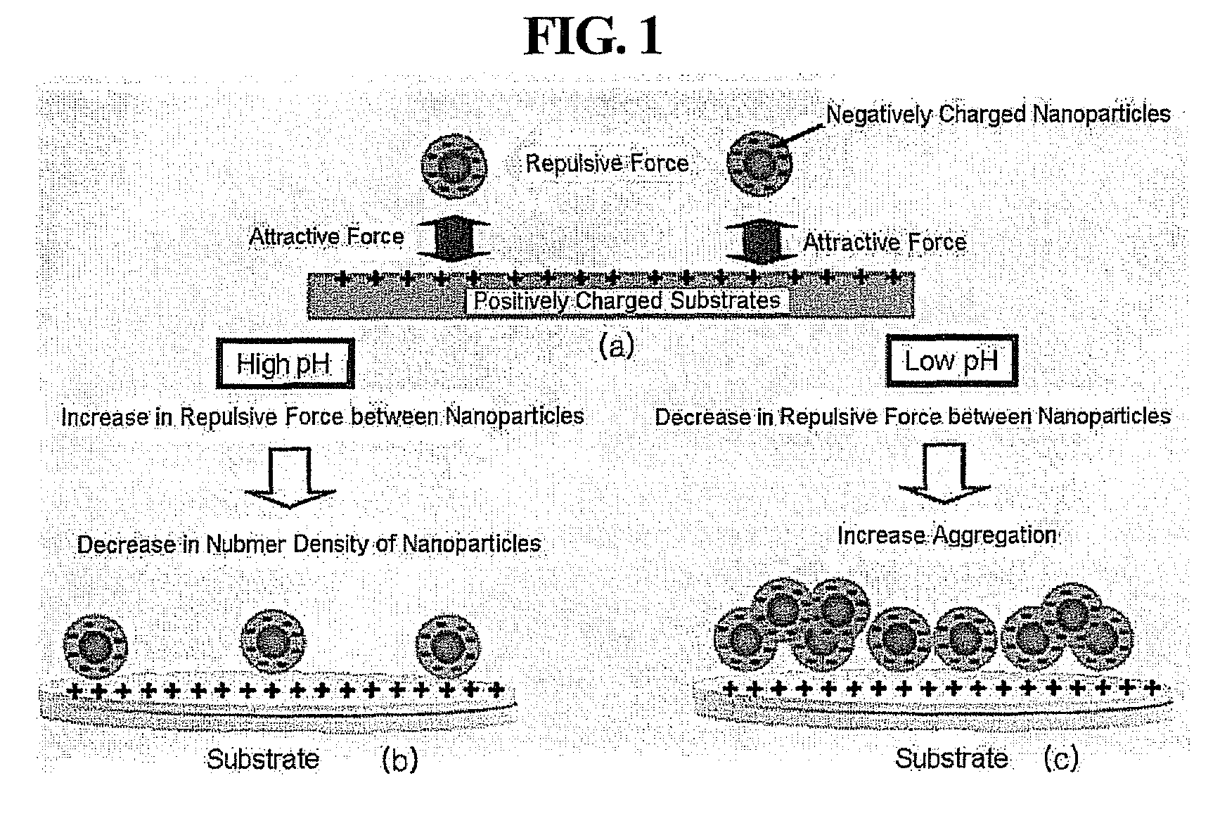
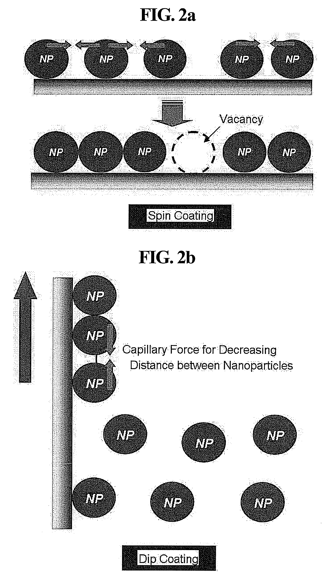
Formation of Nanoparticle Monolayers

[0063]Silicon wafer substrates were dipped in a piranha solution (H2SO4:H2O2 1:3 (volume / volume) (v / v), ultrasonicated for 15 minutes, washed with methanol / toluene, ultrasonicated in an RCA solution (NH4OH:H2O2:H2O=1:1:5 (v / v / v)) at 70° C. for 10 minutes, and sufficiently washed with methanol using distilled water.

[0064]A 10 millimolar (mM) aqueous solution of polyallylamine hydrochloride (PAH, Mw=70,000) was spin-coated at 5,000 revolutions per minute (rpm) on the washed substrates for 30 seconds. The PAH-coated substrates were baked at 150° C. for 10 minutes, and then the respective nanoparticle dispersions having different pH values prepared in Example 2 were spin-coated thereon at 3,000 rpm for 30 seconds to form nanoparticle monolayers. The spin coating was conducted three times and washed using distilled water. The number density of the nanoparticles in each of the nanoparticle monolayers was observed under a scanning electron microscope (SE...


PUM

PropertyMeasurementUnit
reaction temperatureaaaaaaaaaa
temperatureaaaaaaaaaa
sizeaaaaaaaaaa

Abstract

Methods for producing nanoparticle thin films are disclosed. According to one of the methods, a nanoparticle thin film is produced by modifying the surface of nanoparticles to allow the nanoparticles to be charged, controlling an electrostatic attractive force between the charged nanoparticles and a substrate and a repulsive force between the individual nanoparticles by a variation in pH to control the number density of the nanoparticles arranged on the substrate.

Description

BACKGROUND OF THE INVENTION[0001]This non-provisional application claims priority under 35 U.S.C. §119(a) on Korean Patent Application No. 2006-105648 filed on Oct. 30, 2006, which is hereby incorporated in its entirety by reference.[0002]1. Field of the Invention[0003]The present invention relates to a method for dispersing nanoparticles. It also relates to a method for producing nanoparticle thin films by utilizing the dispersed nanoparticles. More specifically, the present invention relates to a method for producing a nanoparticle thin film in which the surface of nanoparticles is modified to allow the nanoparticles to be charged. An electrostatic attractive force between the charged nanoparticles and a substrate and a repulsive force between the individual nanoparticles is controlled by a variation in pH to control the number density of the nanoparticles arranged on the substrate. In addition, a capillary force other than the electrostatic forces is introduced during the arrange...

Claims


Application Information

Patent Timeline
Patent Type & Authority Applications(United States)
IPC IPC(8): B05D3/12B22F1/145
CPCB22F1/0088B22F2998/00Y10T428/268H01L51/0036B22F1/0022B22F1/145H10K85/113B22F1/0545B82B3/00B82Y40/00
Inventor CHOI, SEONG JAECHOI, JAE YOUNGJANG, EUN JOOXAVIER, BULLIARDKANG, YU JINBAE, WAN KICHAR, KOOK HEON
Owner SAMSUNG ELECTRONICS CO LTD
Why Eureka
Try Eureka