Ceramic filter and regenerating method thereof

a ceramic filter and regenerating method technology, applied in the direction of membranes, filtration separation, separation processes, etc., can solve the problems of increasing manufacturing costs, inferior permeation performance of carbonaceous membranes to that of inorganic separation membranes such as silica membranes, etc., to achieve the effect of low cost, easy removal, and low cost of ceramic filter regenerating

Inactive Publication Date: 2008-05-08
NGK INSULATORS LTD
View PDF10 Cites 13 Cited by
  • Summary
  • Abstract
  • Description
  • Claims
  • Application Information

AI Technical Summary

Benefits of technology

[0016]A constitution in which the carbonaceous membrane is formed on the porous base member and the inorganic separation membrane is formed on the carbonaceous membrane is employed. In consequence, in a case where the ceramic filter deteriorates, the filter can thermally be treated to easily remove the carbonaceous membrane and the inorganic separation membrane from the porous base member, and the carbonaceous membrane and the inorganic separation membrane can be formed anew to inexpensively regenerate the ceramic filter. When the inorganic separation membrane is the silica membrane, the number of membrane formation times may be small, and the ceramic filter for dehydration having a high permeation performance and a high separation performance can be obtained.

Problems solved by technology

As the inorganic separation membrane, for example, a silica membrane has a high permeability and a high separability, but in order to form the silica membrane as the separation membrane on the porous base member, four or five types of silica sols having different particle diameters have to be formed into membranes several times, respectively, membrane formation is performed ten or more times in total, and this increases manufacturing costs.
On the other hand, when the carbonaceous membrane is formed on the porous base member, a coating liquid having the same composition may be formed into membranes about several times, the membrane can inexpensively be manufactured, but the permeation performance of the carbonaceous membrane is inferior to that of an inorganic separation membrane such as the silica membrane.

Method used


Image

  • Ceramic filter and regenerating method thereof
  • Ceramic filter and regenerating method thereof
  • Ceramic filter and regenerating method thereof

Examples


examples

[0035]The present invention will hereinafter be described in accordance with examples in more detail, but the present invention is not limited to these examples.

[0036](1) Support Body

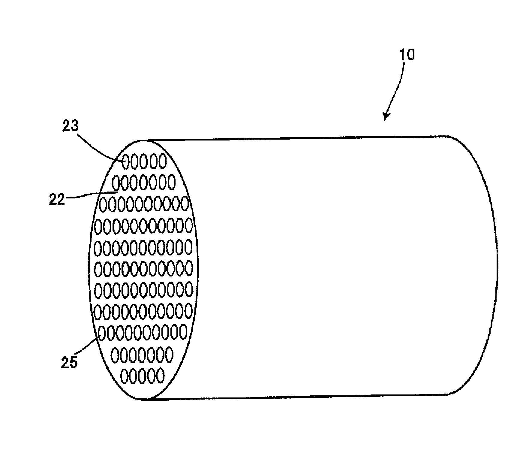
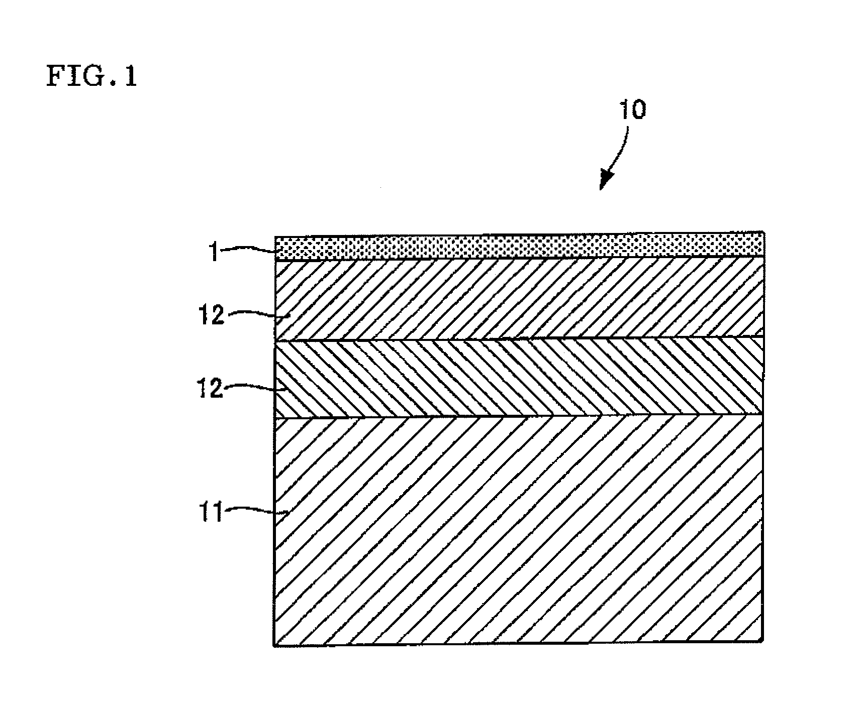
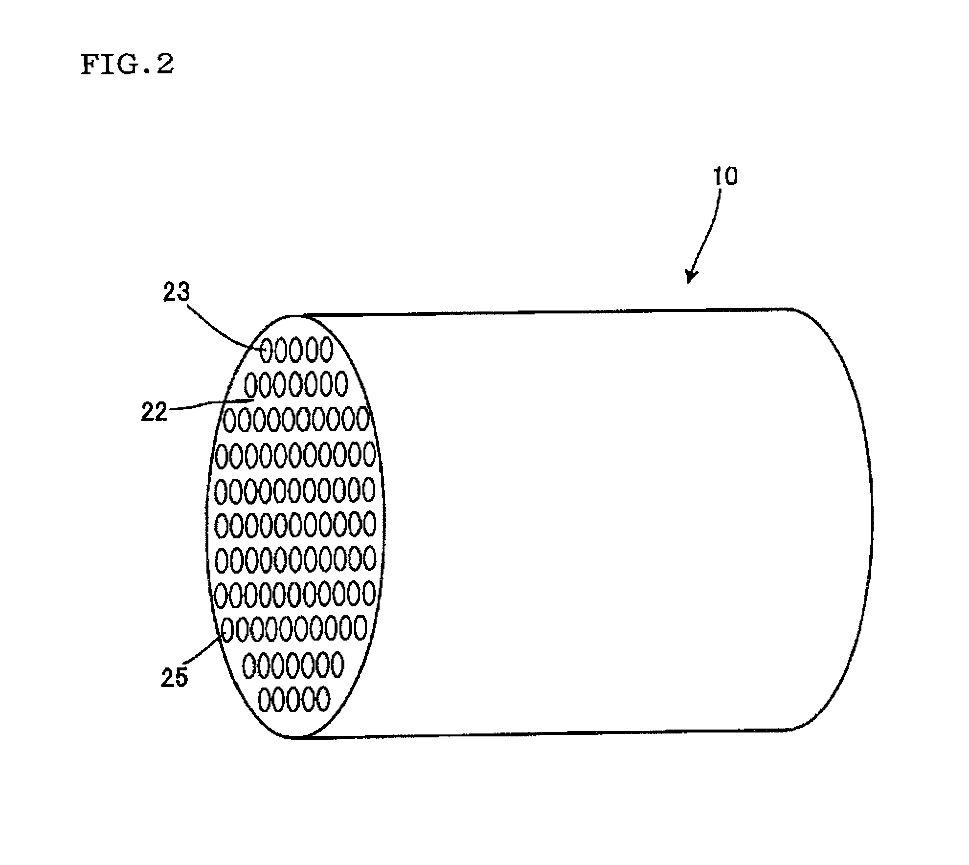
[0037]On an outer surface of an alumina porous base member having an average pore diameter of 5 μm, an outer diameter of 10 mm, an inner diameter of 7 mm and a length of 40 mm, a first porous membrane which was an alumina porous layer having pore diameters of 1 μm and a thickness of 100 μm, and a second porous membrane which was an alumina porous layer having pore diameters of 0.1 μm and a thickness of 20 μm were formed to constitute a support body (a porous base member).

[0038](2) Formation of Carbonaceous Membrane

[0039]Polyamide acid (AURUM (trade name) manufactured by Mitsui Chemicals, Ltd.) as a precursor of polyimide was diluted with N,N-dimethyl acetoamide to obtain a polyamide acid solution (I) having a polyamide acid content of 1 mass %. The support body (1) was hung, submerged into the polyamide...


PUM

PropertyMeasurementUnit
thicknessaaaaaaaaaa
pore diameteraaaaaaaaaa
particle diameteraaaaaaaaaa

Abstract

A ceramic filter includes a porous base member formed of a ceramic porous body, a carbonaceous membrane formed on the porous base member, and an inorganic separation membrane (e.g., a silica membrane) formed on the carbonaceous membrane. As the inorganic separation membrane, instead of the silica membrane, a titania membrane, a zirconia membrane, a zeolite membrane or the like may be used. In a regenerating method of the ceramic filter, the deteriorated ceramic filter is thermally treated to remove the carbonaceous membrane and the silica membrane from the porous base member, then the carbonaceous membrane is formed on the porous base member, and the silica membrane is formed on the carbonaceous membrane.

Description

BACKGROUND OF THE INVENTION AND RELATED ART[0001]The present invention relates to a ceramic filter and a regenerating method of the filter. More particularly, it relates to a ceramic filter formed with less membrane formation times and having a high water permeation performance and a high separation performance, and a regenerating method of the filter.[0002]Heretofore, various methods of forming an inorganic separation membrane on a porous base member have been known. For example, a hot coating process is known (see Non-Patent Document 1). This is a method of rubbing a tube base member with cloth containing a silica sol to apply the sol, thereby forming the inorganic separation membrane on an outer surface of the heated tube base member.[0003]A method of forming the inorganic separation membrane on an inner surface of a porous base member having a tubular shape or a cylindrical lotus-root-like monolith shape by filtering membrane formation is also known (see Patent Document 1). The ...

Claims


Application Information

Patent Timeline
Patent Type & Authority Applications(United States)
IPC IPC(8): B01D29/00B01D29/62
CPCB01D63/066B01D65/02B01D67/0088B01D69/12B01D2321/32B01D71/027B01D71/028B01D2323/08B01D71/024
Inventor ISOMURA, MANABU
Owner NGK INSULATORS LTD
Why Eureka
Try Eureka