
Method of monitoring a photvoltaic generator

a photovoltaic generator and generator technology, applied in the field of photovoltaic generator monitoring, can solve the problems of complex circuits needed to detect electric arcs and high cost, and achieve the effects of optimal theft security, relatively slow current change, and cost advantages

Active Publication Date: 2008-05-08
SMA SOLAR TECH AG
View PDF5 Cites 203 Cited by
  • Summary
  • Abstract
  • Description
  • Claims
  • Application Information

AI Technical Summary

Benefits of technology

[0011] An advantage of the method is that theft monitoring, or protection against manipulation, is also possible in the night hours, i.e., also when the solar generator does not deliver any current.
[0012] The invention is capable of using one single measuring principle for monitoring various damages or manipulations on the generator, including theft of the generator. This offers cost advantages. Moreover, the method of the invention is very reliable since there is no need for complex detection of electromagnetic radiation.
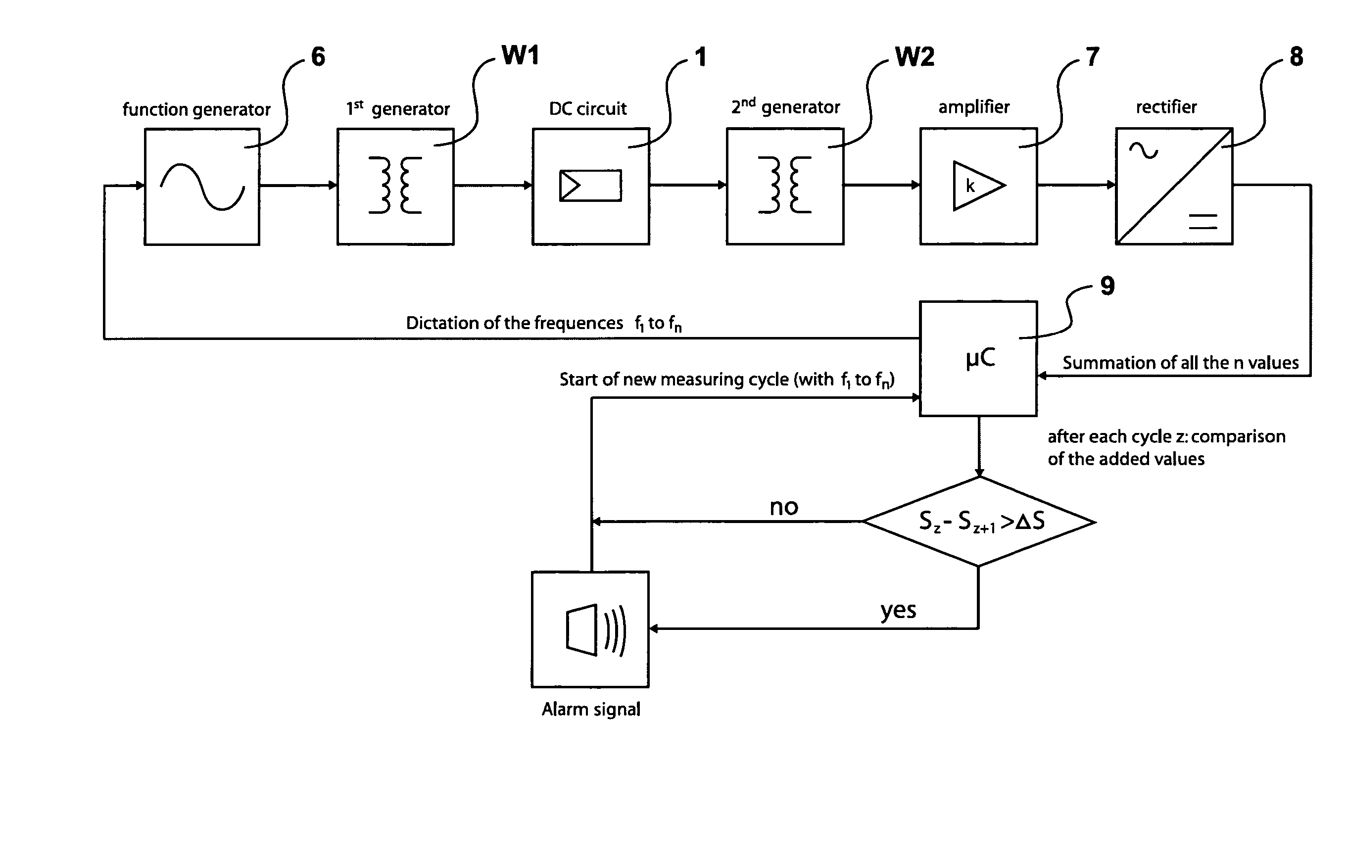
[0013] Theft monitoring with the method of the invention preferably occurs during the night hours only, a second method being utilized during the day hours. The second method uses more specifically a reference sensor, preferably a reference solar generator. This measure provides optimal theft security. During the day, an abrupt current interruption for example is indicative of a theft. A current change occurs relatively slowly, for example when a cloud covers the generator. During the night hours, by contrast, the first method with the frequency response monitoring is utilized as it is very reliable in operation when the solar generator does not generate any current.
[0014] As an alternative, or in addition thereto, the method may also be utilized for electric arc monitoring or for checking defective contacts of the photovoltaic generator. In this way, fires caused by a defective electric contact may be prevented. Instead or in addition to an alarm signal, the solar generator may be switched off when an electric arc occurs.
[0015] A quite simple but still effective developed implementation of the invention is characterized in that an auxiliary variable is formed from measured current or voltage curves and that the change of the auxiliary variable is monitored, an alarm signal occurring when the change of the auxiliary variable exceeds a threshold value. A monitoring circuit may be provided in a quite simple way. It is advantageous if the auxiliary variable is formed from the sum of the measured current or voltage amplitudes or if the auxiliary variable occurs as a result of the integration of the surfaces beneath the measured curves. Both solutions are easy to realize with computer or microprocessor control.
[0016] It is particularly advantageous if the current having a frequency spectrum is fed using a first converter with primary and secondary winding that is connected to the direct current circuit of the generator and if the frequency spectrum is detected using a second converter with primary and secondary winding that is mounted in series with the first converter. As a result, a monitoring circuit may be connected in series to the generator and must be connected to an external connection only. Accordingly, the output of the solar generator virtually constitutes the output of the monitoring circuit. The losses generated by the monitoring circuit are negligible since the direct current drop generated in the converter substantially tends to zero.

Problems solved by technology

The circuits needed to detect electric arcs are complex and expensive though.

Method used


Image

  • Method of monitoring a photvoltaic generator
  • Method of monitoring a photvoltaic generator
  • Method of monitoring a photvoltaic generator

Examples


Embodiment Construction

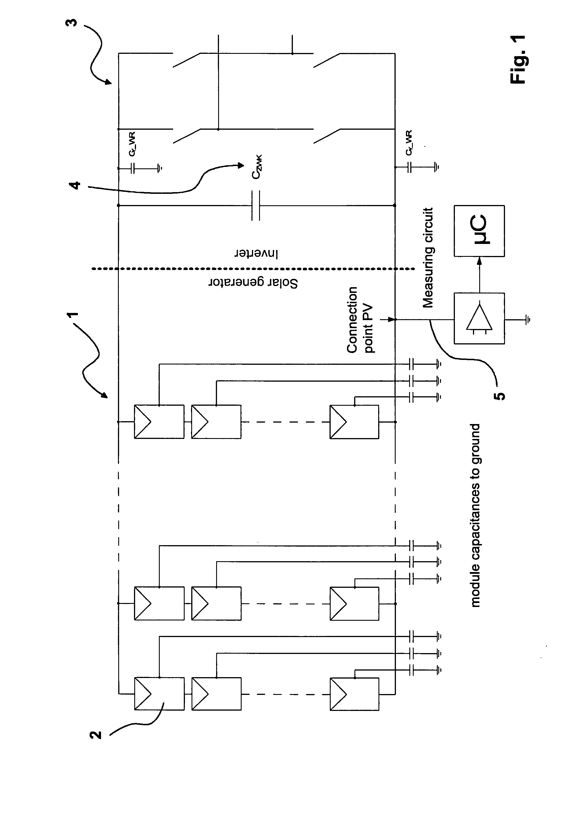
[0029]FIG. 1 shows a photovoltaic plant with a photovoltaic generator 1 with several photovoltaic modules 2 connected in series and in parallel. Between an inverter 3 with input capacitor 4, there is disposed a monitoring circuit 5. Said monitoring circuit is mounted in series with the photovoltaic generator 1 and the inverter in the DC circuit.

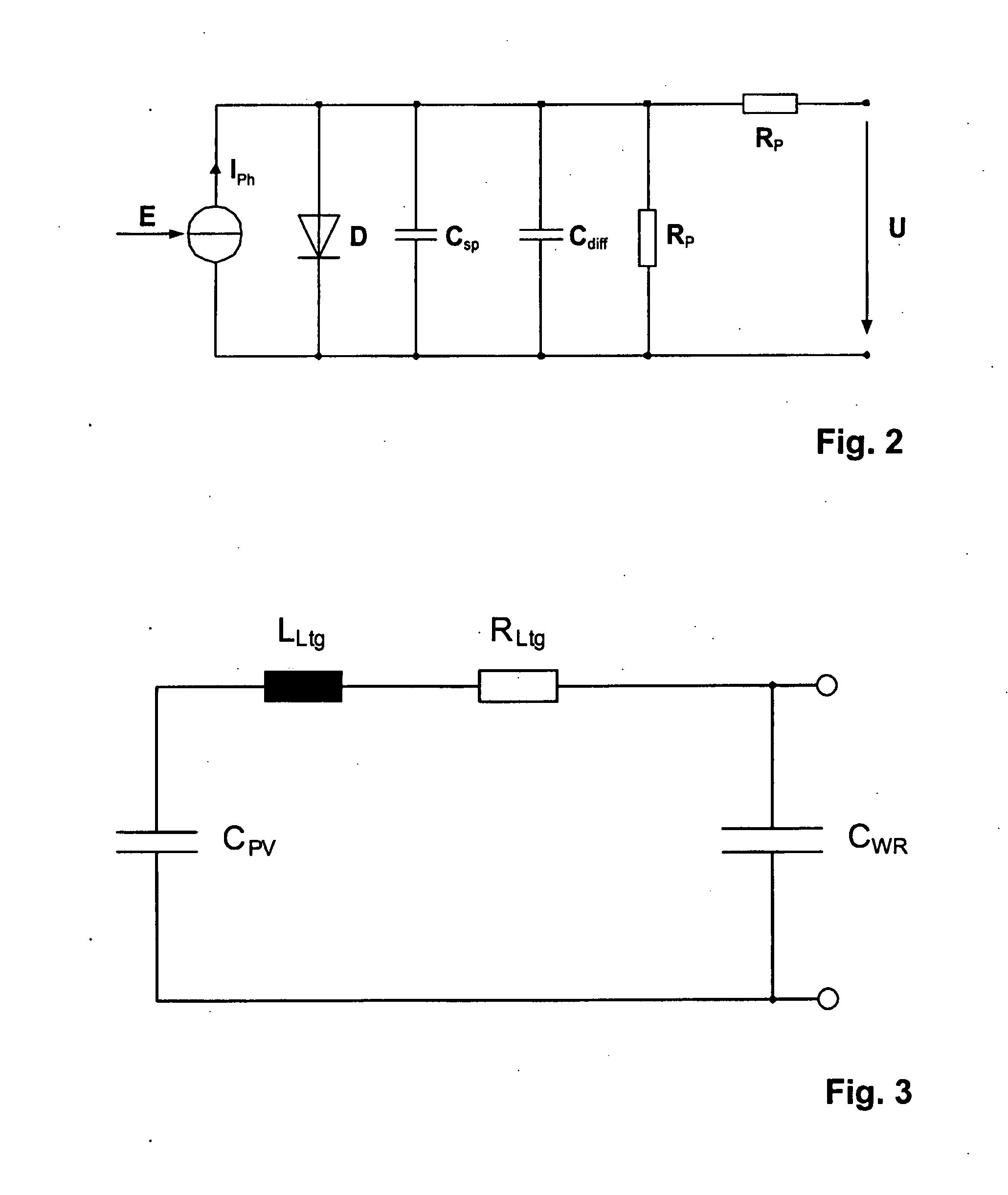
[0030] As shown in FIG. 2, each solar cell has an equivalent circuit diagram with capacitances Csp and Cdiff, with a diode and resistances. The various solar cells are disposed, more specifically in a meandering fashion, in a module that has not been illustrated in closer detail herein so that a quite long current line and, as a result thereof, a significant inductance is achieved as can be seen in the equivalent circuit diagram shown in FIG. 3.

[0031] If one module among a plurality of series connected modules and / or of parallel connected solar modules is removed, for example in the event of a theft, capacitances or inductances change. Sinc...


PUM


Abstract

The subject matter of the present invention is a method for monitoring a photovoltaic generator (1) for generating current with a number of solar cells connected between two external connections by repeated feeding of a current with a frequency spectrum into the generator current circuit, detecting thereby a respective frequency response in the frequency spectrum with the supplied current as the input variable and an electric variable of the generator as the output variable, and detecting a change in the frequency response for monitoring the photovoltaic generator (1) in the event of a change during repeated feeding.

Description

CROSS-REFERENCE TO RELATED APPLICATIONS [0001] This application claims Priority from German Application No. DE 10 2006 052 295.8-34 filed on 3 Nov. 2006 1. FIELD OF THE INVENTION [0002] The invention relates to a method of monitoring a photovoltaic generator for generating current with a number of solar cells connected between two external connections. [0003] For photovoltaic generator theft monitoring it is known to infer theft from abrupt current changes of the generator. The disadvantage thereof is that this method can only be used during the day since the generator does not supply current by night. 2. DESCRIPTION OF THE PRIOR ART [0004] A method of protecting a solar module against unauthorized manipulation or theft is known from DE 101 61 480 B4. This method relies on detecting an interruption in a series connection. An alternative current is thereby supplied. The measuring current supply may also be clocked. By feeding the measuring current at intervals, there is no need for p...

Claims


Application Information

Patent Timeline
IPC IPC(8): G01R23/02
CPCG01R31/02H02S50/10Y10S136/29Y02E10/50
Inventor PRIOR, OLIVERJUCHEM, RALFVICTOR, MATTHIAS
Owner SMA SOLAR TECH AG
Learn More