Process for producing hydrogen with permselective membrane reactor and permselective membrane reactor
a technology of permselective membrane and hydrogen, which is applied in the direction of separation process, dispersed particle separation, chemical apparatus and processes, etc., can solve the problems of hydrogen cannot move smoothly to the permselective membrane, and the catalyst is not activated, so as to reduce the disproportionation of carbon monoxide and increase the efficiency of separating and recovering hydrogen
Active Publication Date: 2008-05-08
NGK INSULATORS LTD
View PDF6 Cites 9 Cited by
- Summary
- Abstract
- Description
- Claims
- Application Information
AI Technical Summary
Benefits of technology
The present invention provides a process for producing hydrogen using a permselective membrane reactor that reduces carbon monoxide and catalyst deactivation caused by disproportionation, and has a high efficiency of separating and recovering hydrogen. The process involves supplying a raw material gas containing ethanol, and a layer composed of a reforming catalyst that promotes reforming of ethanol. The reactor has a gas inlet and a gas outlet, and a separator tube with a permselective membrane selectively permeable to hydrogen. The hydrogen recovery rate is in the range of 60% to 99%, and the ratio of hydrogen to carbon dioxide is in the range of 0.6 to 20. The process is efficient and produces high-quality hydrogen. The invention also provides a permselective membrane reactor that includes a reactor tube, a separator tube, and a layer composed of a reforming catalyst that promotes reforming of ethanol. The membrane reactor has a high efficiency of separating and recovering hydrogen, and the hydrogen recovery rate is in the range of 60% to 99%. The invention also provides a method for producing hydrogen using a permselective membrane reactor that reduces carbon monoxide and catalyst deactivation, and has a high efficiency of separating and recovering hydrogen.
Problems solved by technology
However, in the hydrogen production using the permselective membrane reactors, although the reaction temperature is advantageously reduced, a disproportionation reaction of carbon monoxide expressed by the following reaction formula (3) occurs more frequently, causing deactivation of a catalyst due to coking.
However, while the main cause of coking is a decomposition reaction of a hydrocarbon in the non-membrane reactors, it is the disproportionation of carbon monoxide in the permselective membrane reactors as described above.
Furthermore, because hydrogen produced by a catalytic reaction diffuses through space of a packed catalyst layer, hydrogen cannot move smoothly to the permselective membrane.
This reduces the efficiency of separation and recovery.
Such a problem is particularly significant in permselective membranes having high permeability.
Method used
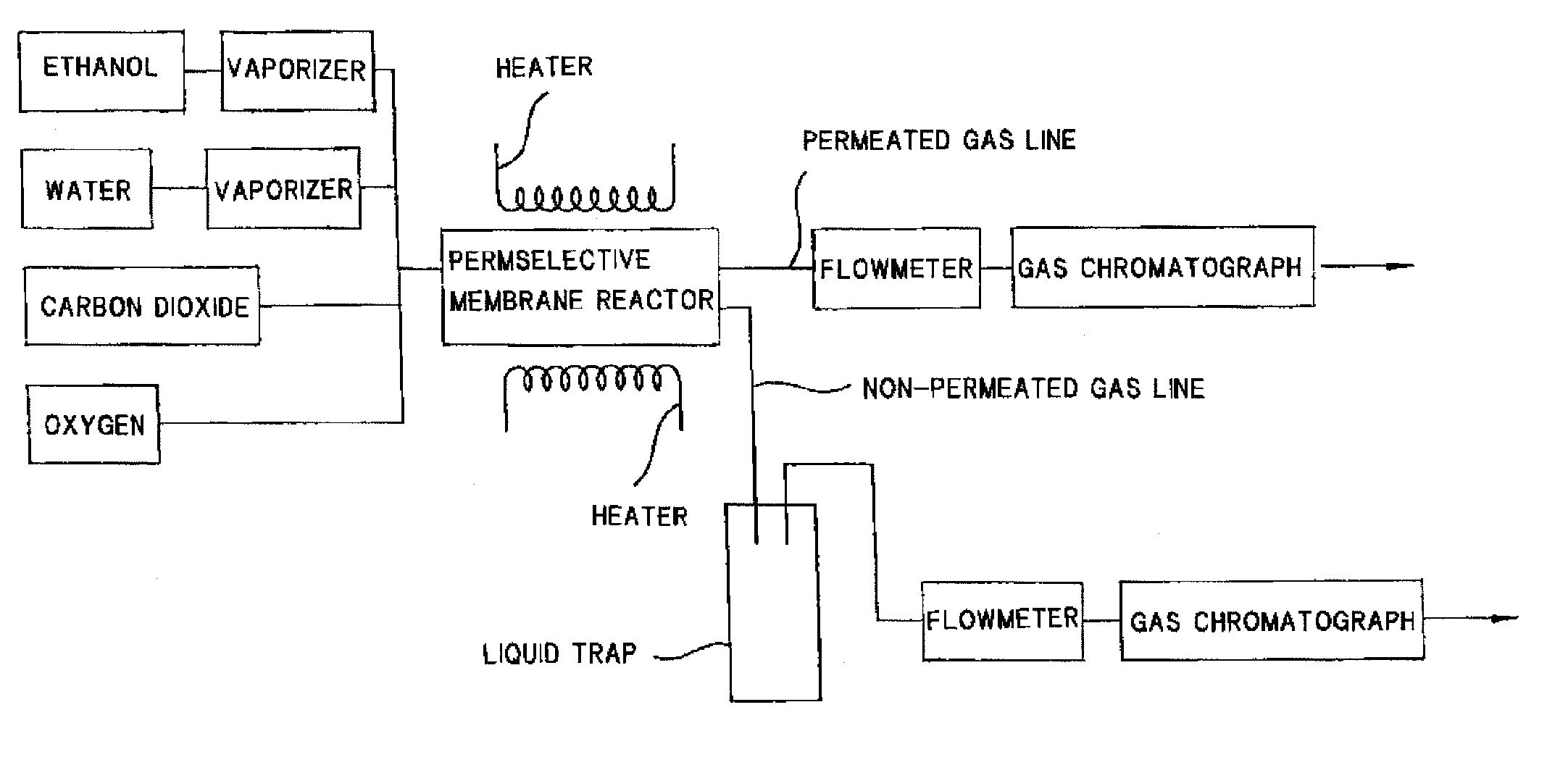
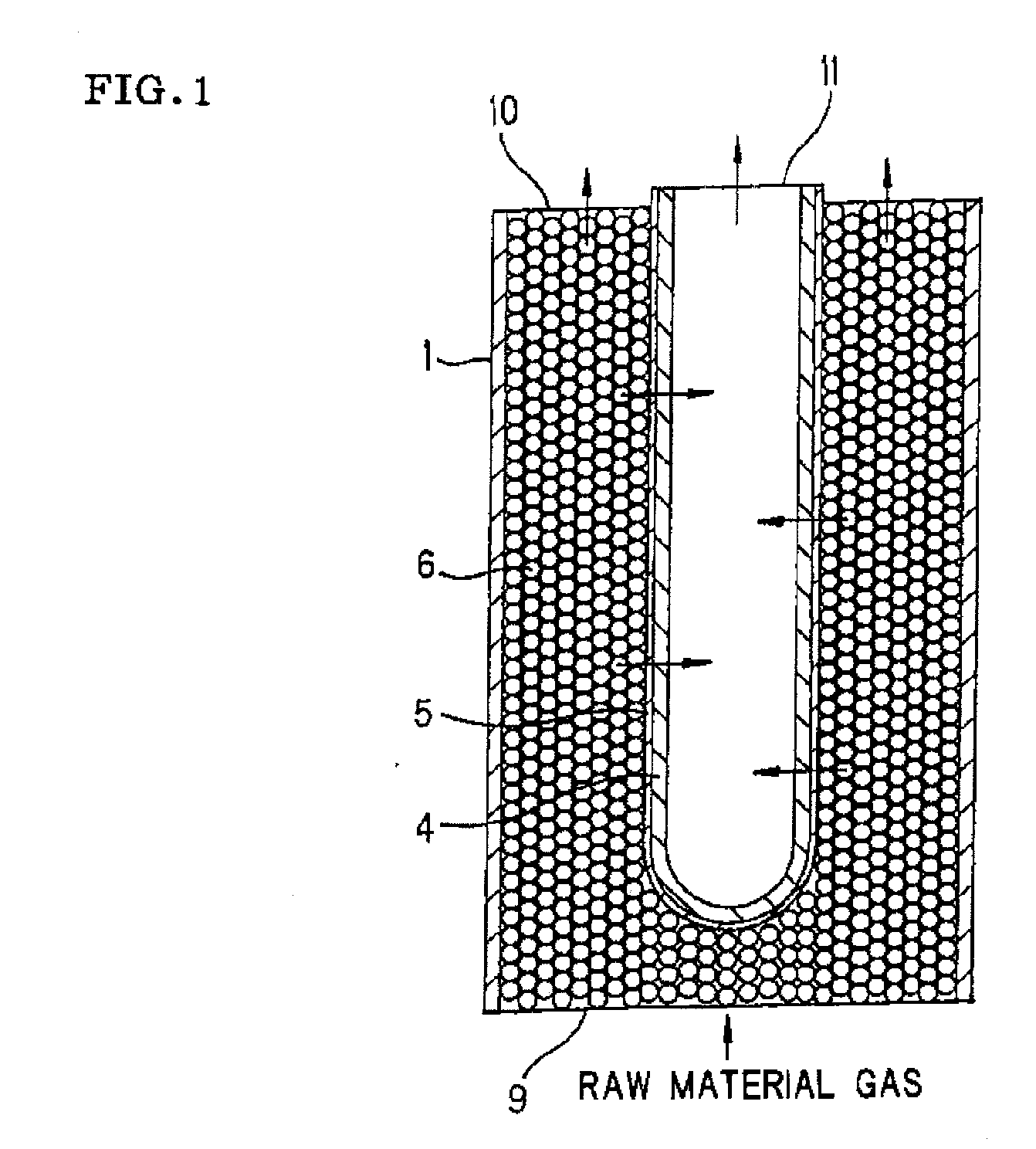
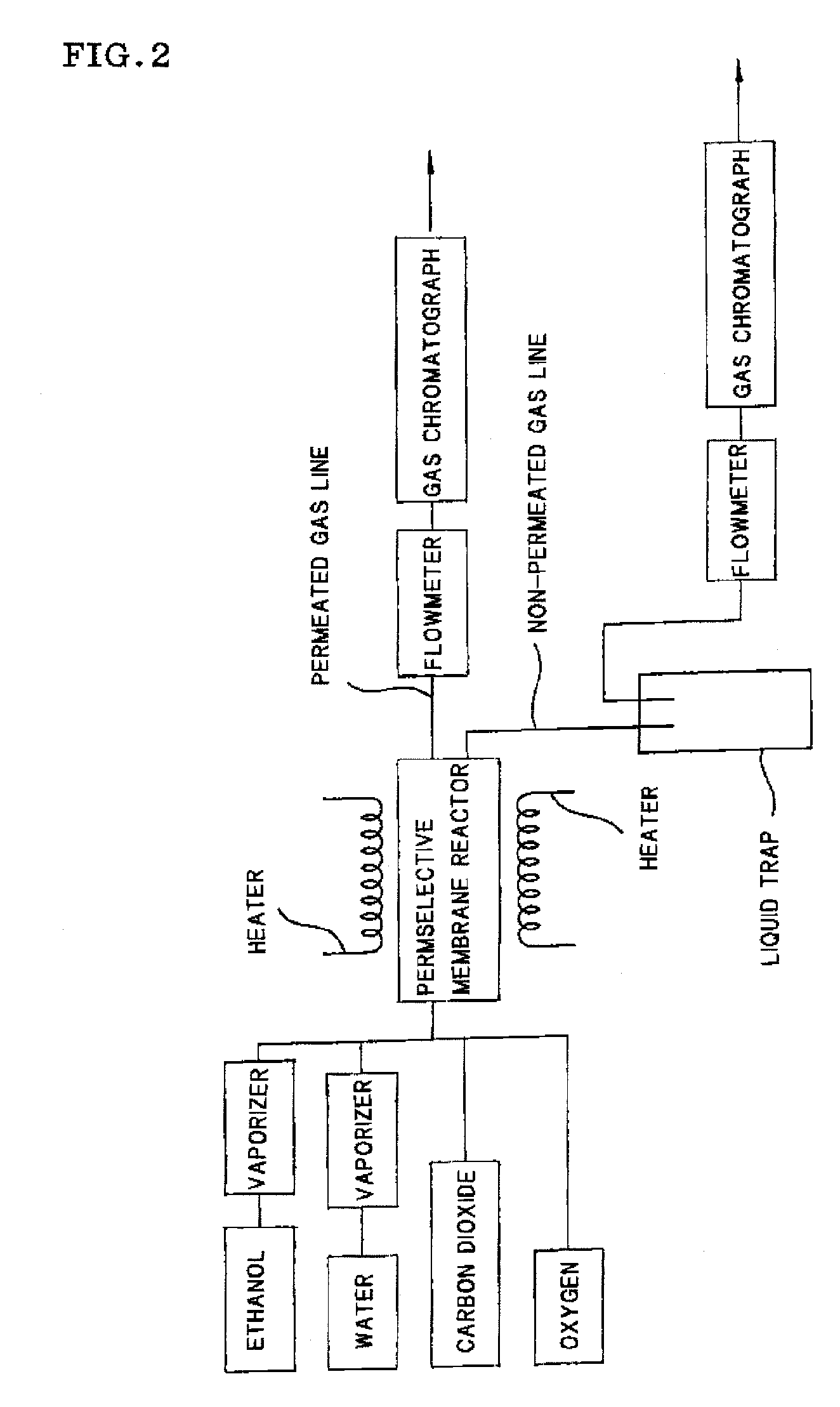
View moreImage
Smart ImageViewing Examples
Examples
examples
[0057] The present invention will now be further described with examples. However, the present invention is not limited to these examples.
Login to View More PUM
| Property | Measurement | Unit |
|---|---|---|
| thickness | aaaaa | aaaaa |
| temperature | aaaaa | aaaaa |
| temperature | aaaaa | aaaaa |
Abstract
In a process for producing hydrogen according to the present invention, hydrogen is produced under conditions where hydrogen recovery rate defined by the following equation is in the range of 60% to 99%: Hydrogen recovery rate=100×{A / (A+B)}wherein A denotes the amount of hydrogen that passes through the permselective membrane (the amount of permeated hydrogen) [ml / min], and B denotes the amount of hydrogen that does not pass through the permselective membrane (the amount of non-permeated hydrogen) [ml / min], and where α defined by the following equation is at least 0.6: α={(CO2) / (CO)2} / K wherein (CO2) denotes the partial pressure of carbon dioxide at the gas outlet of the reactor tube, (CO) denotes the partial pressure of carbon monoxide, and K denotes the equilibrium constant of the disproportionation reaction of carbon monoxide at the internal temperature of the reactor.
Description
TECHNICAL FIELD [0001] The present invention relates to a process for producing hydrogen using a permselective membrane reactor from a raw material gas containing ethanol, and to a permselective membrane reactor that can suitably be used in the process for producing hydrogen. BACKGROUND ART [0002] Hydrogen has been used in large quantities as a basic material gas in petrochemistry. In particular, hydrogen has recently received attention as a clean energy source in fields, such as fuel cells. Thus, hydrogen is expected to find wider use. Hydrogen for use in such applications has been produced by reforming of water vapor or carbon dioxide, a partial oxidation reaction, or a decomposition reaction, from raw materials mainly composed of hydrocarbons, such as methane, butane, and kerosene, and oxygen-containing hydrocarbons (hydrocarbons containing an oxygen atom), such as methanol, ethanol, and dimethyl ether, followed by separation with a permselective membrane that is selectively perm...
Claims
Login to View More Application Information
Patent Timeline
 Patent Type & Authority Applications(United States)
IPC IPC(8): C01B3/38B01J7/02
CPCB01D53/22C01B2203/1229B01J8/009B01J8/025B01J8/0257B01J2208/00415C01B3/323C01B3/505C01B2203/0227C01B2203/0233C01B2203/041C01B2203/047C01B2203/0475C01B2203/048C01B2203/1052C01B2203/1064B01D2257/108
Inventor NAKAMURA, TOSHIYUKIMORI, NOBUHIKO
Owner NGK INSULATORS LTD
Features
- R&D
- Intellectual Property
- Life Sciences
- Materials
- Tech Scout
- Unparalleled Data Quality
- Higher Quality Content
- 60% Fewer Hallucinations
Learn More Browse by: Latest US Patents, China's latest patents, Technical Efficacy Thesaurus, Application Domain, Technology Topic, Popular Technical Reports.
© 2025 PatSnap. All rights reserved.Legal|Privacy policy|Modern Slavery Act Transparency Statement|Sitemap|About US| Contact US: help@patsnap.com


