Dipole Antennas and Coaxial to Microstrip Transitions

a transition and dipole antenna technology, applied in the field offolded dipoles, can solve the problems of increased coupling, unacceptably large number of antennas at each site, increased cost and bulk, etc., and achieve the effect of increasing the rigidity of the dipole box and allowing the spacing between adjacent dipoles to be controlled accurately

Active Publication Date: 2008-05-15
BISON PATENT LICENSING LLC
View PDF9 Cites 62 Cited by
  • Summary
  • Abstract
  • Description
  • Claims
  • Application Information

AI Technical Summary

Benefits of technology

[0017]The concavo-convex geometry of the arms of the folded dipole provide a particularly compact arrangement, enabling the arms to “wrap around” an adjacent region. The sides of the arms may be straight (for instance v-shaped) or curved.
[0021]The retaining elements increase the rigidity of the dipole box, and enable the spacing between the adjacent dipoles to be controlled accurately.

Problems solved by technology

To provide dedicated antennas for each system would require an unacceptably large number of antennas at each site.
An unbalanced feed can lead to unbalanced currents on the dipole arms which can cause beam skew in the plane of polarization (vertical pattern for a v-pole antenna, horizontal pattern for a h-pole antenna, vertical and horizontal patterns for a slant pole antenna), increased cross-polar isolation in the far field and increased coupling between polarizations for a dual polarized antenna.
A disadvantage of a stripline arrangement is that a pair of ground planes is required, resulting in additional expense and bulk.
Firstly, the integrity of the joint cannot be guaranteed.
Secondly, it is necessary to construct the microstrip line from a metal which allows the solder to flow.
Direct soldering to the ground plane has the disadvantages given above, and also the further disadvantage that the ground plane will act as a large heat sink, requiring a large amount of heat to be applied during soldering.

Method used


Image

  • Dipole Antennas and Coaxial to Microstrip Transitions
  • Dipole Antennas and Coaxial to Microstrip Transitions
  • Dipole Antennas and Coaxial to Microstrip Transitions

Examples


second embodiment

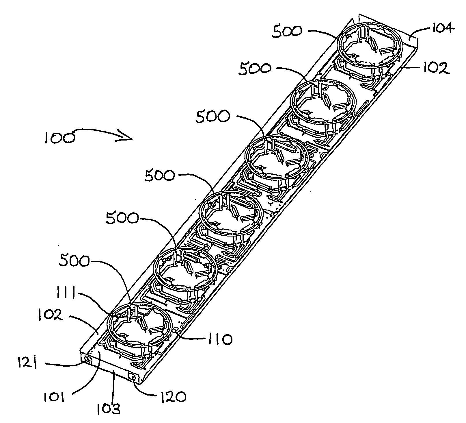
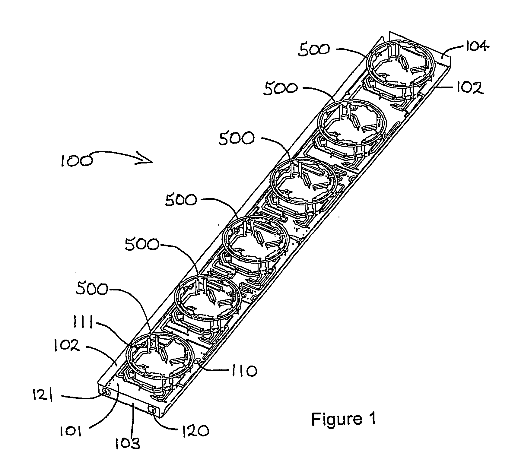
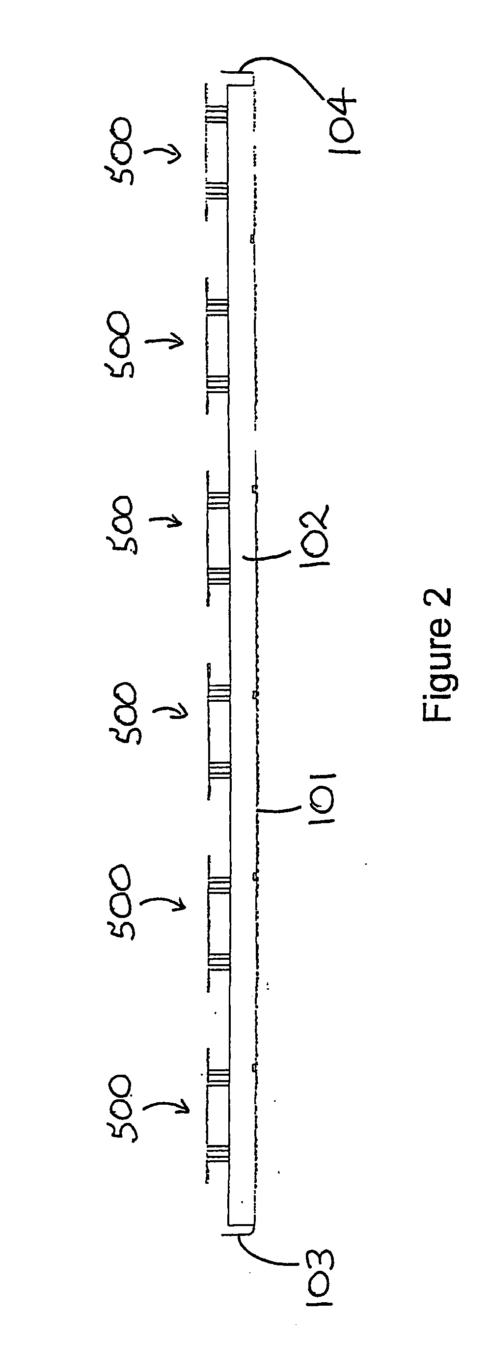
[0131]FIG. 8 shows a single dual polarization folded dipole antenna module 800 according to the present invention. The ground plane and dielectric spacers are not shown. The antenna module 800 is identical to the module 500 shown in FIG. 5, except it is provided as a single self-contained module with inputs 840 and 841.

[0132]In a variable downtilt antenna (not shown), a number of single modules 800 can be arranged in a line and ganged together with cables, circuit-board splitters, and variable differential phase shifters for adjusting the phase between the modules. For instance, the differential phase shifters described in US2002 / 0126059A1 and US2002 / 0135524A1 may be used.

[0133]The transition coupling the coaxial transmission line 360 with the RF input section 340 is shown in FIGS. 9-13. The coaxial transmission line 360 has a central conductor 361 and a cylindrical coaxial conductive sheath 362 separated from the central conductor by a dielectric 363. An insulating jacket 364 enclo...

third embodiment

[0148]Referring now to FIG. 17 a third embodiment is shown which is a modification of the embodiment shown in FIG. 15. Like integers have been given like numbers. In this embodiment two additional arrays of cross dipoles have been added to the embodiment shown in FIG. 17. A first array of cross dipoles 1040, 1041 and 1042 is provided to the left and a second array of cross dipoles 1043, 1044 and 1045 is provided to the right. By adjusting power division or phase shift between first array 1040, 1041 and 1042, second array 1023-1028 and third array 1043-1045, beam width may be adjusted or azimuth steering may be provided. Various feed arrangements for adjusting beam width or effecting azimuth and / or downtilt steering are disclosed in the Applicant's PCT application no. PCT / NZ01 / 00137, the disclosure of which is hereby incorporated by way of reference. Such techniques may also be utilised with the multi array embodiments described hereafter. Beam width / angle control may be effected usi...

sixth embodiment

[0152]FIG. 20 shows a sixth embodiment comprising a first array of dipole rings for operation over a first frequency band and a second array of dipole rings 1066, 1067 and 1068 operable over a second frequency band having a mid-frequency higher than the mid-frequency of the first frequency band. All dipole rings employ curvilinear folded dipoles of substantially quarter circle segments. The arrangement has good symmetry and thus good isolation characteristics.

[0153]The further embodiment shown in FIG. 21 is similar to the embodiment shown in FIG. 20 except that additional high band dipole rings 1069 and 1070 are provided in the gaps between low frequency dipole rings 1071-1073. The array of high frequency dipole rings 1074, 1069, 1075, 1070 and 1076 may be spaced so as to avoid grating lobes. It will be appreciated that additional high frequency band dipole rings may be placed between low frequency band dipole rings in other embodiments herein described also.

[0154]Referring now to F...


PUM


Abstract

The invention relates in part to a folded dipole having a dipole axis and a pair of arms which together have a profile which is concave on one side and convex on the other when viewed along the dipole axis. The dipoles may be arranged as a dipole box around a central region, typically in a generally circular or square configuration. Further elements may be placed in the dipole box or in the gaps between dipole boxes. The antenna may be a single-band antenna, or a multi-band antenna with the further elements operating in a different frequency band to the dipole boxes. The further elements may be concentric dipole boxes. The invention is particularly suited for use in a cellular base station panel antenna. A novel coaxial to microstrip transition is also described.

Description

CROSS-REFERENCE TO RELATED APPLICATIONS[0001]This application claims the benefit of priority from copending U.S. application Ser. No. 10 / 390,487, filed on Mar. 17, 2003, entitled Folded Dipole Antenna, Coaxial To Microstrip Transition, And Retaining Element, and claims the benefit of priority from U.S. Provisional Patent Application Ser. No. 60 / 433,352, filed on Dec. 13, 2002, entitled Improvements Relating To Dipole Antennas. Provisional Patent Application Ser. No. 60 / 433,352 is incorporated herein by reference in its entirety.FIELD OF THE INVENTION[0002]The present invention relates to a folded dipole, a dipole box, an antenna incorporating an array of dipole boxes, a method of manufacturing a dipole, and an electrically insulating element for retaining together a pair of dipoles. The invention also relates to a coaxial to microstrip transition All aspects of the invention are typically but not exclusively for use in wireless terrestrial mobile communications systemsBACKGROUND OF ...

Claims


Application Information

Patent Timeline
Patent Type & Authority Applications(United States)
IPC IPC(8): H01Q9/26H01Q21/20H01P5/103H01Q1/24H01Q3/26H01Q5/00H01Q5/42H01Q5/48H01Q9/28H01Q21/24
CPCH01P5/103H01Q1/246H01Q3/26H01Q5/48H01Q9/285H01Q21/24H01Q5/42H01Q9/26
Inventor BISIULES, PETER JOHNCOULT, JOHNYANG, CHING-SHUNGAVILAN, JOSELITO DE LA CRUZDENG, GANG YIWILSON, JOHN STEWART
Owner BISON PATENT LICENSING LLC
Why Eureka
Try Eureka