
Pattern Forming Process

a pattern and forming technology, applied in the field of pattern forming process, can solve the problems of deformation of the tent layer protecting the hole portion, deformation of the clear pixels, and deformation of the image formed on the pattern forming material, and achieve the effect of fine and efficient forming, reducing image distortion, and reducing the distortion of the imag

Inactive Publication Date: 2008-05-15
FUJIFILM CORP
View PDF1 Cites 16 Cited by
  • Summary
  • Abstract
  • Description
  • Claims
  • Application Information

AI Technical Summary

Benefits of technology

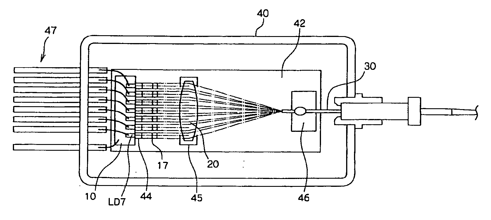
[0015]The present invention aims to provide a pattern forming process which allows finely and efficiently forming permanent patterns such as interconnection patterns and highly achieving both tent property and resolution by curbing distortions of images to be formed on pattern forming materials having at least a photosensitive layer.

Problems solved by technology

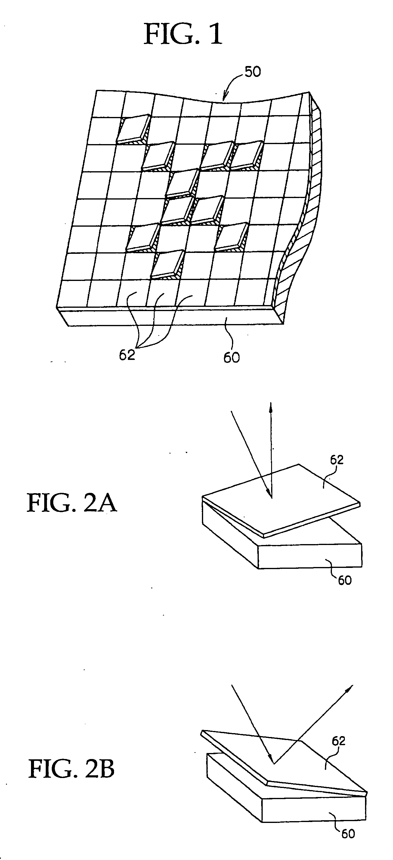
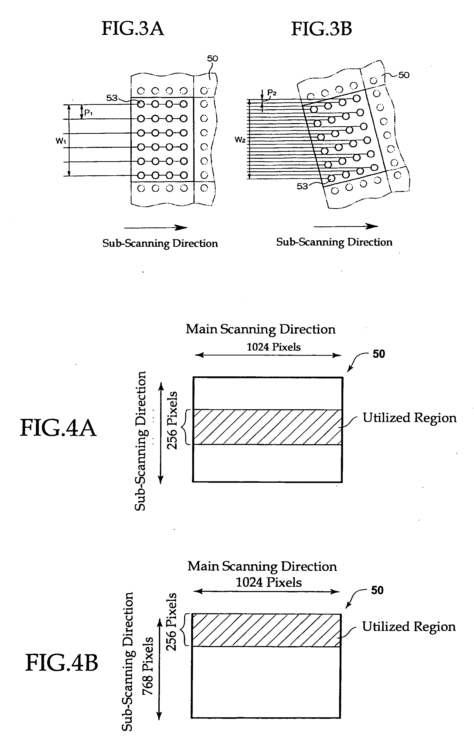
However, the means to solely direct the modulated light from the spatial light modulator into the magnified imaging optical system leads to magnify the light flux from the respective imaging portions of the spatial light modulator, resulting in a disadvantage that clearness of pixels decreases due to magnified pixel size within the projected pattern.
However, these proposals suffer from a problem that images formed on the pattern forming materials are deformed through utilizing the laser beam collected by the microlenses of the array.
The problem is significant in particular when the DMD is utilized as the spatial light modulator.
When the thickness of a photosensitive layer on a hole portion such as a through hole or a via hole of a printed circuit board, it causes a problem that a tent layer protecting the hole portion tears in the process of dissolving and removing unhardened portions and in the process of etching exposed metal layer portions.

Method used


Image

  • Pattern Forming Process
  • Pattern Forming Process
  • Pattern Forming Process

Examples


example 1

Production of Laminate

—Production of Pattern Forming Material—

[0571]A photosensitive resin composition solution composed of the following composition was applied over a surface of polyethylene terephthalate film 20 μm in thickness as the support, and the surface of the support was dried to form a photosensitive layer 15 μm in thickness, thereby the pattern forming material was produced.

Methylmethacrylate / 2-ethylhexyl acrylate / benzyl methacrylate / methacrylic acid copolymer (composition15 parts by massof copolymer (mass ratio)): 50 / 20 / 7 / 23; mass average molecular mass: 90,000; and acid value 150)Polymerizable monomer represented by the following Structural Formula (73)7.0 parts by massAdduct of ½ molar ratio of hexamethylene diisocyanate and tetraethylene oxide monomethacrylate7.0 parts by massN-methylacridone0.11 parts by mass2,2-bis(o-chlorophenyl)-4,4′,5,5′-tetraphenylbiimidazole2.17 parts by mass2-mercaptobenzimidazole0.23 parts by massmalachite green oxalate0.02 parts by massleuk...

example 2

[0603]A pattern forming material was produced in the same manner as in Example 1 except that a hexamethylene diisocyanate and tetraethyleneoxide mono-methacrylate adduct at a molar ratio of 1 / 2 of the photosensitive resin composition solution was changed to a compound represented by the following Structural Formula (74). The shortest developing time was 10 seconds, and the light energy amount required to harden the photosensitive layer was 3 mJ / cm2. The compound represented by the Structural Formula (74) is an example of the compound represented by the Structural Formula (24).

A pattern similar to the pattern in Example 1 was formed on the pattern forming material, and the laminate with the pattern formed thereon was evaluated as to resolution, exposing speed, and etching property. Table 3 shows the results. Further, a printed wiring board was produced in the same manner as in Example 1, a pattern was formed by increasing the energy amount of light applied to the through hole portion...

example 3

[0604]A pattern forming material was produced in the same manner as in Example 1 except that a hexamethylene diisocyanate and tetraethyleneoxide mono-methacrylate adduct at a molar ratio of 1 / 2 of the photosensitive resin composition solution was changed to a compound represented by the following Structural Formula (75). The shortest developing time was 10 seconds, and the light energy amount required to harden the photosensitive layer was 3 mJ / cm2. The compound represented by the Structural Formula (75) is an example of the compound represented by the Structural Formula (22).

[0605]A pattern similar to the pattern in Example 1 was formed on the pattern forming material, and the laminate with the pattern formed thereon was evaluated as to resolution, exposing speed, and etching property. Table 3 shows the results. Further, a printed wiring board was produced in the same manner as in Example 1, a pattern was formed by increasing the energy amount of light applied to the through hole p...


PUM


Abstract

The present invention aims to provide a pattern forming process which allows efficiently, highly precisely forming of a permanent pattern such as interconnection patterns and also allows achieving both tent property and resolution at high level. The pattern forming process includes laminating a photosensitive layer on a substrate to be processed in a pattern forming material which comprises at least the photosensitive layer, and exposing two or more arbitrarily selected regions in the photosensitive layer with light of a different amount of energy, wherein a laser beam emitted from a light irradiating unit having ‘n’ imaging portions receiving light from a light irradiating unit and outputting the light is modulated before the photosensitive layer is exposed with the laser beam through a microlens array in which microlenses each having a non-spherical surface capable of compensating the aberration due to distortion of output surfaces of the imaging portions are arrayed.

Description

TECHNICAL FIELD[0001]The present invention relates to a pattern forming process in which laser beams modulated by a light modulating unit such as a spatial light modulator are imaged on pattern a forming material thereby exposing the pattern forming material, and the resulting patterns produced by the pattern forming processes.BACKGROUND ART[0002]Exposing devices have become popular in which lights or laser beams modulated by spatial light modulators and the like are directed to imaging optical systems and optical images are formed on pattern forming materials so as to expose the pattern forming materials. Typically, such exposing devices are provided with a spatial light modulator that is equipped with planar arrays of many imaging portions that modulate an incident light or laser beam depending on various controlling signals, a laser source that irradiates a laser beam to the spatial light modulator, and an imaging optical system that forms an image from the modulated laser beam t...

Claims


Application Information

Patent Timeline
IPC IPC(8): G03F7/207G03F7/004G03F7/20H01L21/027H05K3/00
CPCG03F7/70275H05K3/0082G03F7/70291G02B26/0833
Inventor TAKASHIMA, MASANOBUISHIKAWA, HIROMISHIMOYAMA, YUJI
Owner FUJIFILM CORP
Learn More