Intravascular Ultrasound Imaging Device

a technology of ultrasound imaging and intravascular ultrasound, which is applied in the direction of sound producing devices, sensors, and using reradiation, etc., can solve the problems of electromagnetic noise in the environment in which an ivus operates and the inability to use ivus catheters in general

Inactive Publication Date: 2008-05-15
BIOSCAN
View PDF5 Cites 93 Cited by
  • Summary
  • Abstract
  • Description
  • Claims
  • Application Information

AI Technical Summary

Benefits of technology

[0014]In accordance with an embodiment of the invention, optical energy is transmitted along the ring core to the absorbing material in pulses of light, hereinafter “power light”, that propagate along the ring core in propagation modes characterized by relatively higher order radial indices. (A propagation mode is characterized by radial and angular indices that scale and define the radial and angular dependence respectively of the electromagnetic field that characterizes the propagation mode. The angular index gives the order of the angular symmetry of the field. The radial index is the order of a Bessel function that describes the radial dependence of the field.) The inventors have noted that for light pulses that propagate in higher radial order propagation modes, a relatively large portion of the optical energy in the pulses occupies regions of the ring core close to the outer surface of the core. The increased optical energy density near to the outer surface of the ring core improves absorption of optical energy from the light pulses by the absorber.

Problems solved by technology

Often, the environment in which an IVUS operates is electromagnetically noisy and electromagnetic noise picked up by control and / or data lines in an IVUS catheter reduces signal to noise of the IVUS catheter.
Also, because of its size, an IVUS catheter cannot in general be used to guide another catheter, such as a balloon therapy catheter or stent implant catheter, through the vascular system to provide real time imaging of a region of a blood vessel in which the other catheter is being used to perform corrective intervention.

Method used


Image

  • Intravascular Ultrasound Imaging Device
  • Intravascular Ultrasound Imaging Device
  • Intravascular Ultrasound Imaging Device

Examples


Embodiment Construction

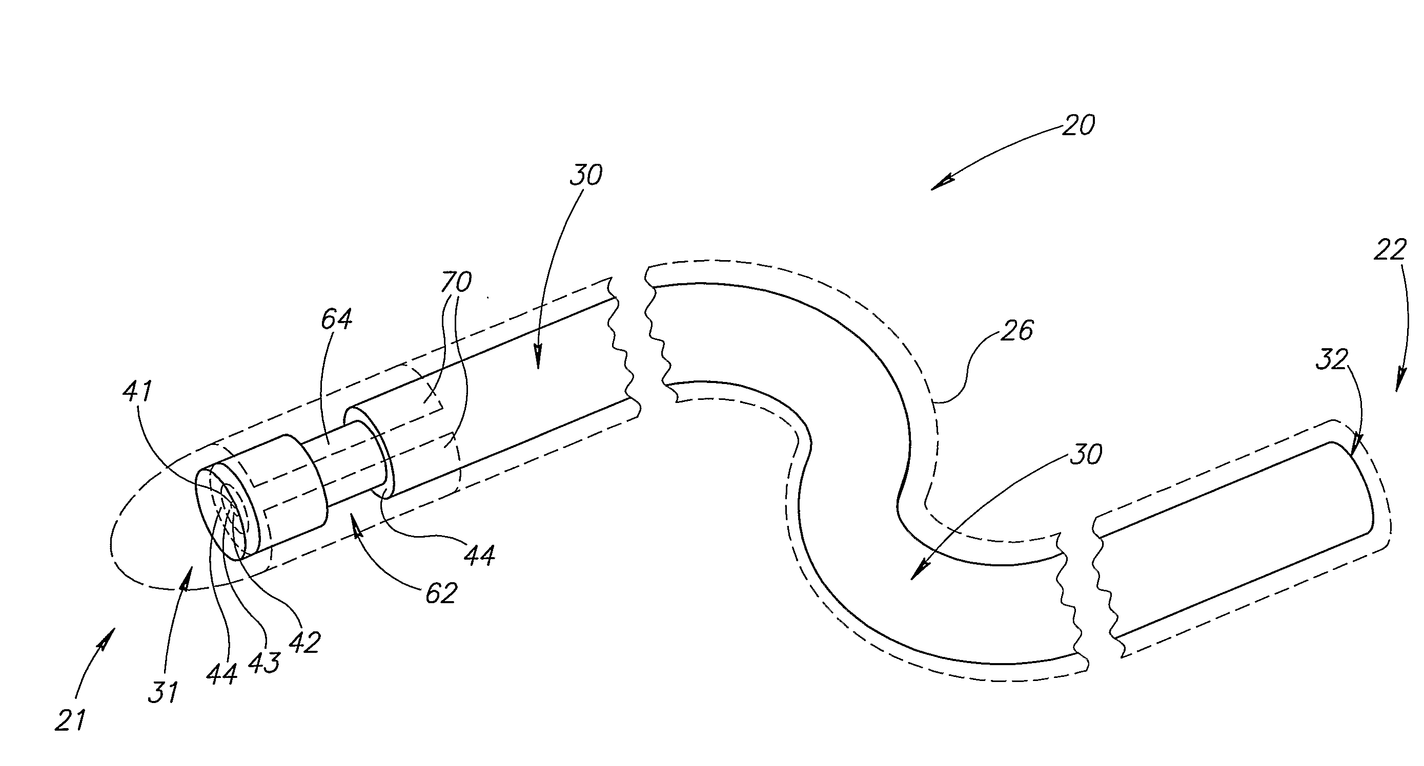
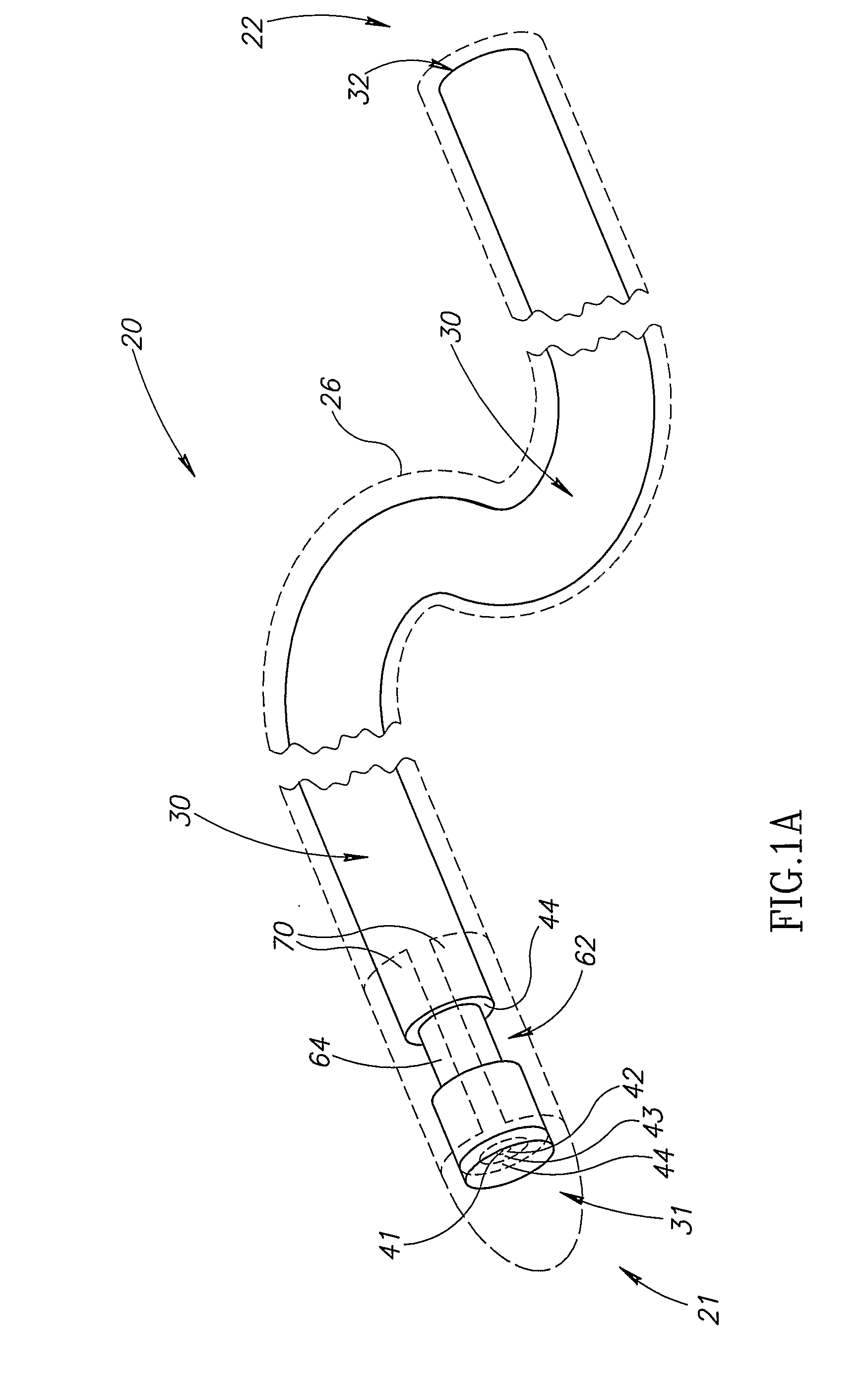
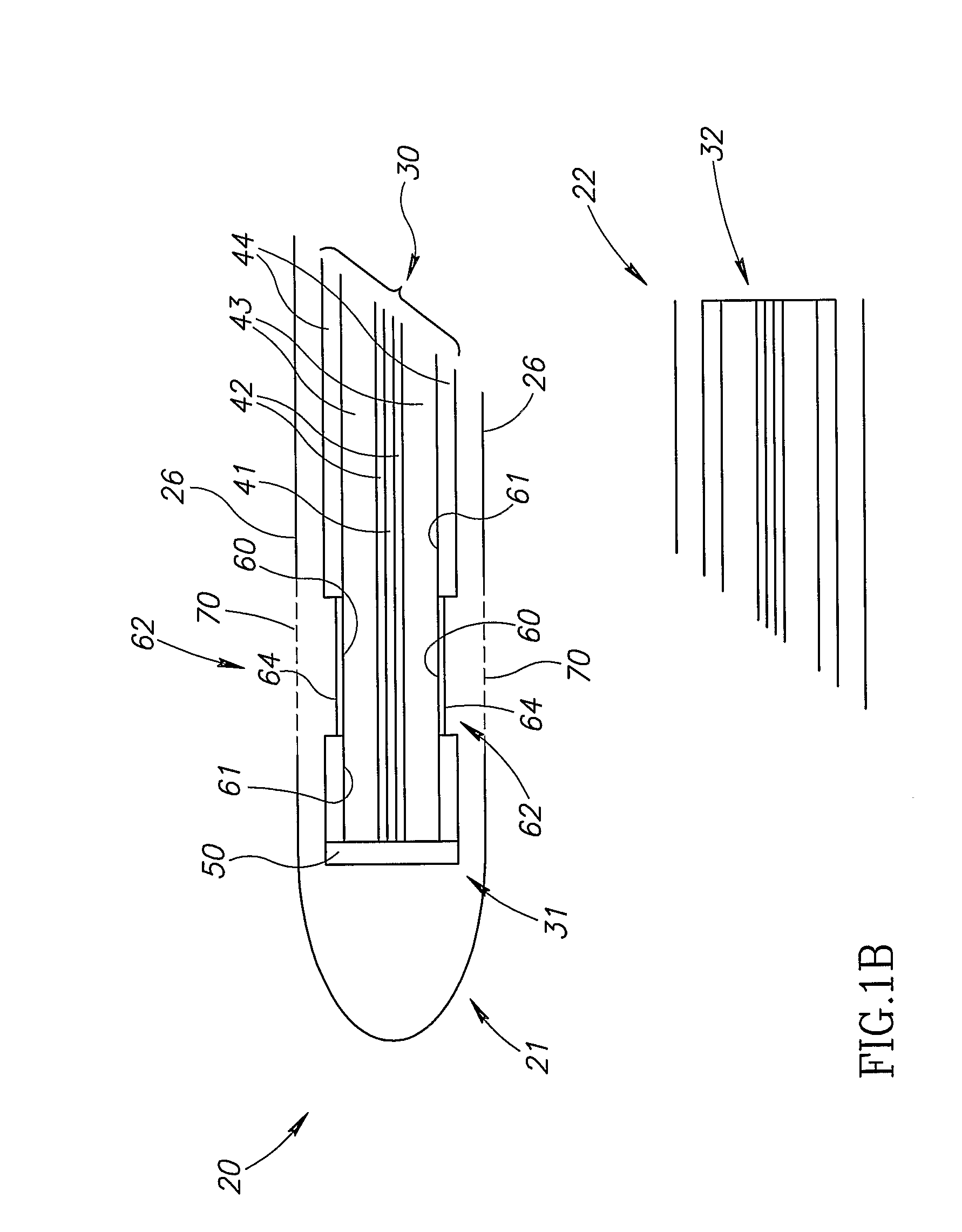
[0055]FIG. 1A schematically shows a perspective view of an IG 20 having a distal end 21 and a proximal end 22, in accordance with an embodiment of the invention. IG 20 optionally comprises an outer guide tube 26 shown in dashed lines and a dual transmission fiber 30 adapted for transmitting ultrasound into a lumen and for receiving echoes of the transmitted ultrasound.

[0056]To facilitate threading IG 20 through the vascular system and positioning its distal end 21 in a region of a vessel to be examined, guide tube 26 is optionally formed from metal or a suitable polymer such as polyimide using any of various methods and devices known in the art so that it functions as a guidewire. To this end, guide tube 26 is relatively flexible and bendable near distal end 21 so that IG 20 may be controlled to negotiate bends and turns in the vascular system. The guide tube gradually becomes more rigid and less bendable towards proximal end 22 to provide the IG with “pushability”. Optionally, guid...


PUM


Abstract

An optic fiber adapted for ultrasound imaging of the lumen of a vessel comprising: an inner core for transmitting light having an index of refraction that changes responsive to acoustic energy incident thereon; a ring core concentric with the inner core for transmitting light; a cladding material between the inner and ring cores that has an index of refraction smaller than the index of refraction of the material from which the inner core is formed; and at least one acoustic transducer comprising absorbing material formed on the surface of the ring core that absorbs optical energy transmitted along the ring core and generates ultrasound responsive thereto.

Description

FIELD OF THE INVENTION[0001]The invention relates to methods and apparatus for determining characteristics of a lumen of a conduit, for example of the lumen of a vessel in the body.BACKGROUND OF THE INVENTION[0002]To assess an extent to which the lumen of a vessel in a patient's body, such as a blood vessel, a bile duct or the urethra, is damaged by disease and, if damaged, advisability of medical intervention to alleviate and / or correct the damage, it is generally required to assess topology of the lumen. For example, to determine an extent to which atherosclerosis damages a blood vessel in the patient's body, it is generally required to determine blood vessel diameter and where and to what extent the blood vessel is narrowed by atherosclerotic plaque.[0003]Often an intravascular ultrasound (IVUS) catheter is used to provide information characterizing the condition of a region of a blood vessel (or other vessel) in the body and provide topographical information of the blood vessel ...

Claims


Application Information

Patent Timeline
Patent Type & Authority Applications(United States)
IPC IPC(8): A61B8/00
CPCA61B5/0097A61B8/12G10K15/046A61M2025/0166G01S15/8968A61B8/4483
Inventor MATCOVITCH, AVRAMKHACHATUROV, ARKADYVOITSECHOV, YURYBAR-LEV, ZVIJAPHA, YONATHANHASSON, SALAH
Owner BIOSCAN
Why Eureka
Try Eureka