Glow plug and method for manufacturing the same

a technology of glow plugs and plugs, which is applied in the direction of engine starters, machines/engines, light and heating apparatus, etc., can solve the problems of ceramic heaters that cannot be easily damaged, ceramic heaters can not be easily damaged, and the center pole can possibly break, so as to reduce internal stress, and reduce the effect of internal stress

Inactive Publication Date: 2008-06-19
NGK SPARK PLUG CO LTD
View PDF5 Cites 12 Cited by
  • Summary
  • Abstract
  • Description
  • Claims
  • Application Information

AI Technical Summary

Benefits of technology

[0022]Further, if a small-diameter portion is provided on the outer peripheral surface of the center pole, and the vibration preventing member is provided on the small-diameter portion as in the above-described third aspect of the invention, it is possible to secure, as the thickness of the vibration preventing member, a size in which the depth of the small-diameter portion is added to the dimension of the clearance between the inner peripheral surface of the axial hole of the metal shell and the outer peripheral surface of the center pole. In the case where resonance occurs in the heater / center pole integrated member, the vibration preventing member is pressed by being clamped between the center pole and the inner peripheral surface of the metal shell, and an internal stress is produced therein. However, if the vibration preventing member is formed with such a large thickness, the vibration preventing member is able to sufficiently contract to alleviate the internal stress, making it possible to obtain a sufficient vibration preventing effect.
[0023]In addition, if the vibration preventing member is provided on the outer peripheral surface of the above-described small-diameter portion after the surface is subjected to processing so as to increase its surface roughness as in the above-described fourth aspect of the invention, the vibration preventing member can be fixed to the small-diameter portion more reliably. As a result, the positional offset of the vibration preventing member can be reliably prevented, and it is possible to maintain a state in which the vibration preventing member is disposed at a position where the vibration amplitude of the heater / center pole integrated member can be suppressed more effectively in the axial direction of the center pole.
[0024]If the combustion chamber is deformed due to the combustion pressure of the internal combustion engine during operation of the internal combustion engine, the leading end side of the glow plug, which is mounted with its heater member exposed toward the combustion chamber, is subjected to pressure. At this time, since the metal shell is compressed in the axial direction between its leading end side and a threaded portion disposed on the rear end side, deformation such as radial bulging or flexing in a direction perpendicular to the axial direction can occur in the metal shell. In that case, a gap is produced between the inner peripheral surface of the metal shell and the vibration preventing member disposed on the surface of the center pole. Accordingly, if the vibration preventing member is press fitted in advance into the metal shell, and is disposed in a radially compressed state as in the above-described fifth aspect of the invention, the gap produced by deformation of the metal shell is filled by the vibration preventing member which bulges with the release of the compressive pressure, so that the vibration preventing effect can be maintained.
[0025]It is, of course, time-consuming to press fit the vibration preventing member into the metal shell in the process of manufacturing the glow plug. Accordingly, if the thickness of the leading end side of the vibration preventing member, which is the side inserted into the metal shell after the rear end side, is formed to be greater than that of the rear end side, as in the above-described sixth aspect of the invention, a situation is prevented in which the vibration preventing member is caught by an edge of the axial hole of the metal shell to cause difficulty in inserting the same. In addition, since friction with the inner peripheral surface of the metal shell can be reduced during the course of inserting the vibration preventing member deep into the interior of the metal shell, smooth insertion can be carried out.
[0026]It should be noted that the vibration preventing member is preferably located at a position different from the position corresponding to the thread forming position as in the above-described seventh aspect of the invention. Generally, the position where the thread is formed on the metal shell is less susceptible to deformation of the combustion chamber, and the inside diameter practically does not change; however, at the position where the thread is not formed, there is a high possibility that the inside diameter changes. In the case where the vibration preventing member is disposed to correspond with the thread forming position, the vibration preventing member is maintained in a compressed state, and it is difficult for the vibration preventing member to exhibit resiliency. However, if the vibration preventing member is disposed to correspond to an axial position where the thread is not present, the compressed state of the vibration preventing member is released in tune with deformation of the metal shell. As such, the vibration preventing member can be made to effectively and easily absorb energy, i.e., a so-called damper effect. Therefore, it is possible to effectively prevent vibration of the heater / center pole integrated member.
[0027]Further, in the above-described vibration preventing member, preferably, as described in the above-noted tenth aspect of the invention, after the small-diameter portion is formed on the center pole, and the outer peripheral surface of the small-diameter portion is subjected to processing so as to increase its surface roughness, the vibration preventing member is formed by injection molding. If the vibration preventing member is formed by such a manufacturing method, the vibration preventing member can be reliably fixed on the small-diameter portion, and the time and trouble involved in managing the thickness of the vibration preventing member can be mitigated. Also, a vibration preventing member capable of suppressing the vibration amplitude of the center pole can be easily formed on the outer peripheral surface of the center pole.

Problems solved by technology

Hence, a possibility has arisen that resonance can frequently occur which is undesirable.
In addition, the greater the amplitude the greater the deflection of the center pole, such that the center pole can possibly break.
Furthermore, the ceramic heater may break due to internal stress transmitted from the center pole.

Method used


Image

  • Glow plug and method for manufacturing the same
  • Glow plug and method for manufacturing the same
  • Glow plug and method for manufacturing the same

Examples


examples

[0084]In a first example, a simulation analysis was conducted to specifically define a desirable state of the strength of the heater / center pole integrated member 9, namely, its mechanical rigidity.

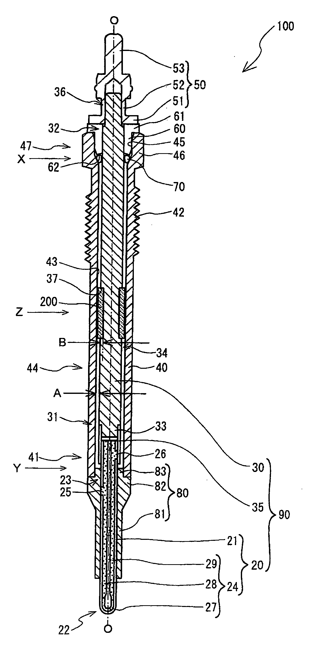
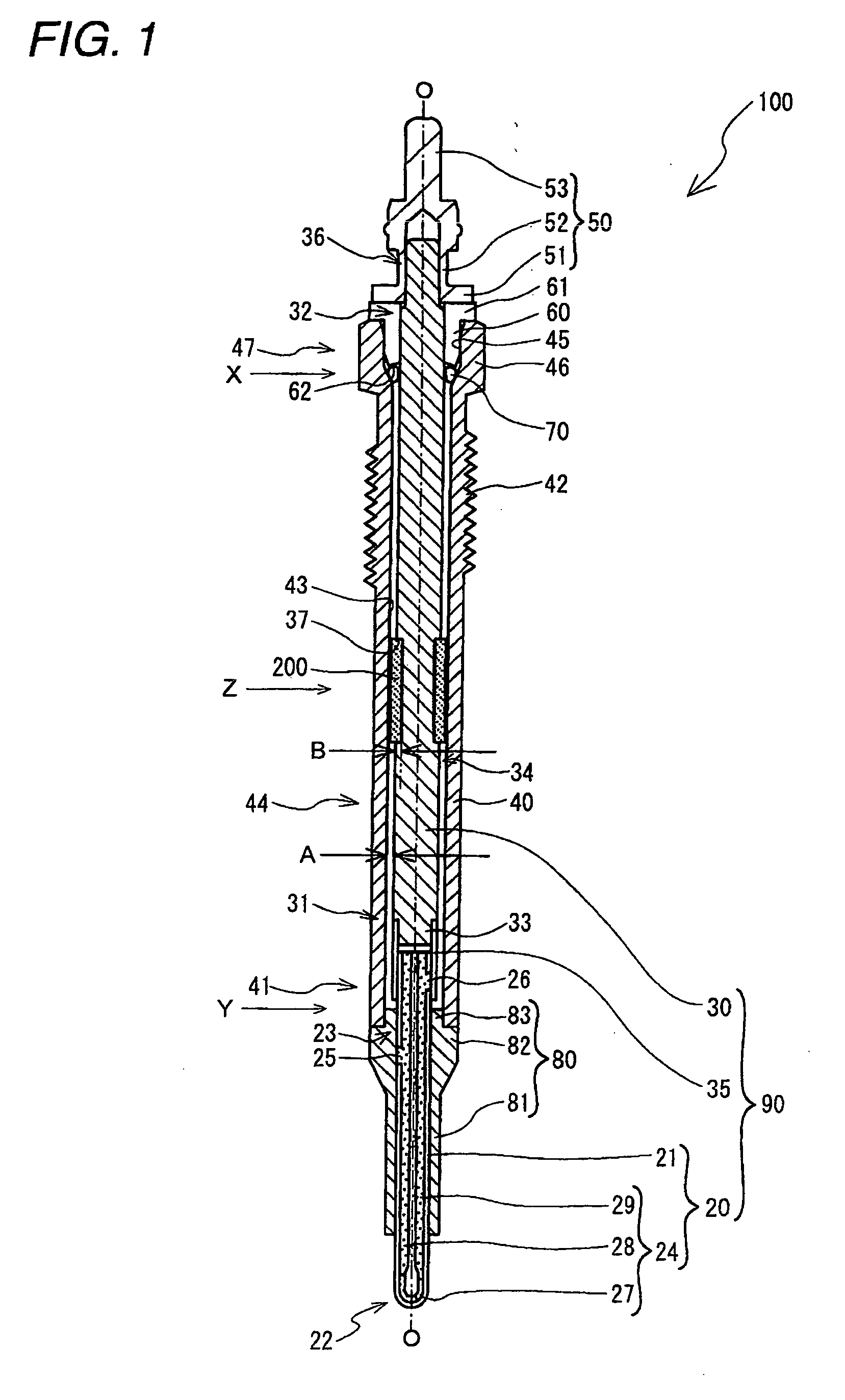
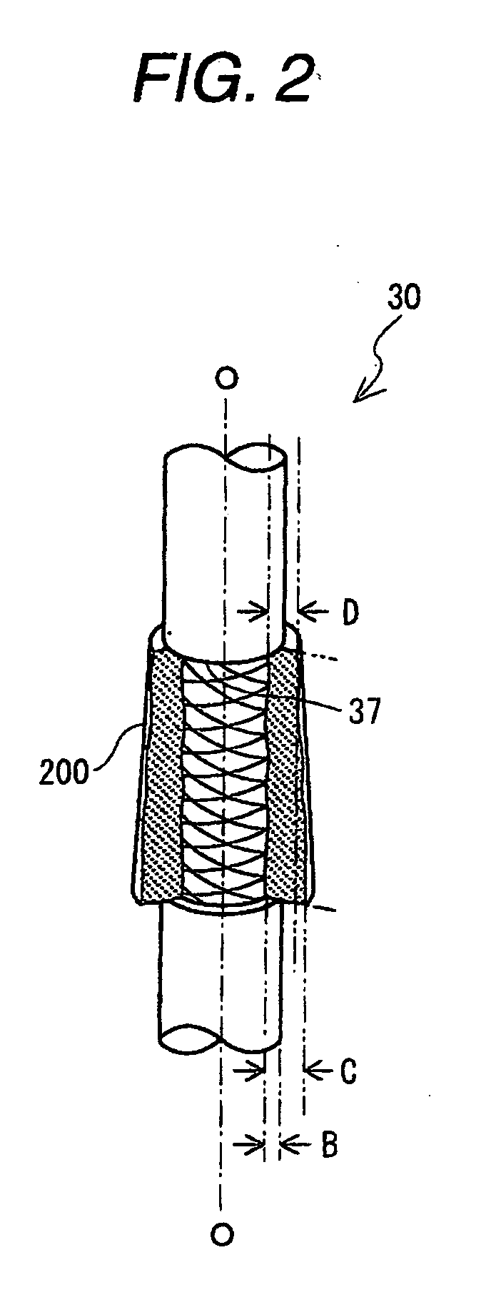
[0085]A first model of the solid cylindrical heater / center pole integrated member 90, formed of SUS 430 and having a constricted portion (a reduced outside-diameter portion FIG. 11) with an outside diameter of Φ1.0 mm corresponding to the small-diameter portion 37, was simulated. As shown in FIG. 1, this first model was prepared as having a large outside diameter relative to the constricted portion to facilitate an understanding of the strength of the constricted portion, while setting the weight of the portion excluding the constricted portion to be identical to that of the heater / center pole integrated member. In the drawing, the side located leftwardly of the constricted portion and having a large mass corresponds to the leading end side of the heater / center pole integrated member 90.

[...


PUM

PropertyMeasurementUnit
angleaaaaaaaaaa
weightaaaaaaaaaa
angle of deformationaaaaaaaaaa

Abstract

A glow plug including a center pole extending along an axial direction; a heater including a heating element capable of generating heat upon energization, which heater is connected to a leading end portion of the center pole so as to constitute together with the center pole an integrated heater/center pole member in a mechanically rigid state; a metal shell as defined herein; and a vibration preventing member for preventing vibration of the center pole, the vibration preventing member being fixed on an outer peripheral surface of the center pole at an axial position corresponding to a portion where an inside diameter of the axial hole of the metal shell is constant.

Description

BACKGROUND OF THE INVENTION[0001]1. Field of the Invention[0002]The present invention relates to a glow plug for assisting start-up of a diesel engine and a method for manufacturing the same.[0003]2. Description of the Related Art[0004]Conventionally, a glow plug used for assisting start-up of a diesel engine has a metallic tubular metal shell, in which a rod-like heater is directly or indirectly held on a leading end side of its axial hole such that a leading end portion of the heater projects therefrom. In addition, a metallic rod-like center pole projects from a rear end side of the metal shell, and is held in the axial hole so as to be electrically insulated from the metal shell. A pair of electrodes for energizing the heater are electrically connected to the metal shell and the center pole, respectively.[0005]The diesel engines in which glow plugs having the above-described structure are used are undergoing a shift toward direct injection type diesel engines in place of convent...

Claims


Application Information

Patent Timeline
Patent Type & Authority Applications(United States)
IPC IPC(8): F23Q7/00F02N19/04
CPCF23Q7/001Y10T29/49087F23Q2007/004
Inventor ITOH, SHINSUKEYOSHIKAWA, TAKAYA
Owner NGK SPARK PLUG CO LTD
Why Eureka
Try Eureka