
Differential-pressure dual ion trap mass analyzer and methods of use thereof

a mass analyzer and dual-ion trap technology, applied in the field of mass spectrometers, can solve the problems of reducing resolution, reducing the kinetic energy of buffer gas, and reducing the efficiency of mass spectral performan

Active Publication Date: 2008-06-19
THERMO FINNIGAN
View PDF22 Cites 53 Cited by
  • Summary
  • Abstract
  • Description
  • Claims
  • Application Information

AI Technical Summary

Benefits of technology

The present invention provides a dual-trap mass analyzer with two regions of different pressures, which allows for efficient ion trapping, cooling, and fragmentation at high pressures while also enabling isolation and mass-sequential scans at low pressures. The high-pressure region promotes high-resolution mass spectra and the use of higher scan rates while maintaining comparable m / z resolutions. The lower pressure region also allows for higher resolution ion isolation. The dual-trap mass analyzer may be operated in different modes and utilizes various techniques for dissociation or reaction, such as photodissociation, ETD, ECD, and PTR. Overall, the invention provides a more effective and efficient tool for mass analysis.

Problems solved by technology

First, the buffer gas reduces the ions' kinetic energy via collisions.
It is known, however, that collisions of ions with buffer gas during the ion isolation and mass-sequential ejection processes may be detrimental to mass spectral performance, both by reducing resolution and by contributing to chemical mass shifts that limit mass accuracy.
It is noted that the problem of chemically dependent mass shifts, which may increase significantly with lowered q ejection values in certain ion traps and under certain conditions, may present a potential obstacle to the use of reduced-q resonant ejection.
Chemically dependent mass shift can be lessened by reducing the buffer gas pressure, but doing so has a substantial adverse effect on the ability to trap and cool ions, and to efficiently fragment ions via the CAD mechanism.
However, the time needed to repeatedly change and stabilize the ion trap pressure may significantly lengthen the overall mass analysis cycle time and reduce sample throughput, particularly where high-capacity ion traps are employed.
The complexity of the mass analysis technique disclosed in the Zerega et al. paper, as well as the need to execute several mass analysis cycles to generate a mass spectrum, disfavor commercial use of this apparatus.

Method used


Image

  • Differential-pressure dual ion trap mass analyzer and methods of use thereof
  • Differential-pressure dual ion trap mass analyzer and methods of use thereof
  • Differential-pressure dual ion trap mass analyzer and methods of use thereof

Examples


Embodiment Construction

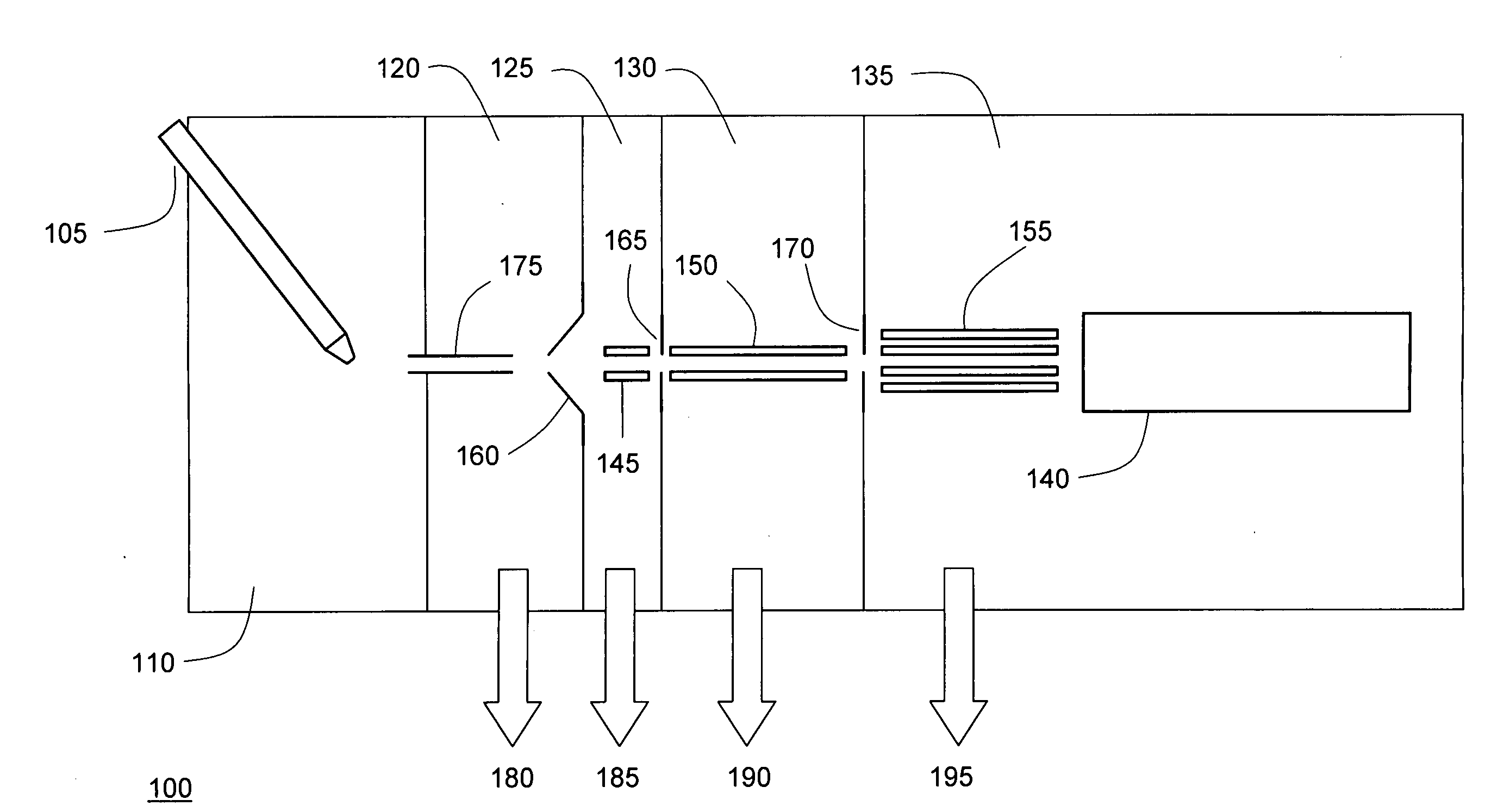
[0017]FIG. 1 depicts the components of a mass spectrometer 100 in which a differential-pressure dual ion trap mass analyzer may be implemented, in accordance with an embodiment of the present invention. It will be understood that certain features and configurations of mass spectrometer 100 are presented by way of illustrative examples, and should not be construed as limiting the differential-pressure dual ion trap mass analyzer to implementation in a specific environment. An ion source, which may take the form of an electrospray ion source 105, generates ions from an analyte material, for example the eluate from a liquid chromatograph (not depicted). The ions are transported from ion source chamber 110, which for an electrospray source will typically be held at or near atmospheric pressure, through several intermediate chambers 120, 125 and 130 of successively lower pressure, to a vacuum chamber 135 in which differential-pressure dual ion trap mass analyzer 140 resides. Efficient tr...


PUM


Abstract

A dual ion trap mass analyzer includes adjacently positioned first and second two-dimensional ion traps respectively maintained at relatively high and low pressures. Functions favoring high pressure (cooling and fragmentation) may be performed in the first trap, and functions favoring low pressure (isolation and analytical scanning) may be performed in the second trap. Ions may be transferred between the first and second trap through a plate lens having a small aperture that presents a pumping restriction and allows different pressures to be maintained in the two traps. The differential-pressure environment of the dual ion trap mass analyzer facilitates the use of high-resolution analytical scan modes without sacrificing ion capture and fragmentation efficiencies.

Description

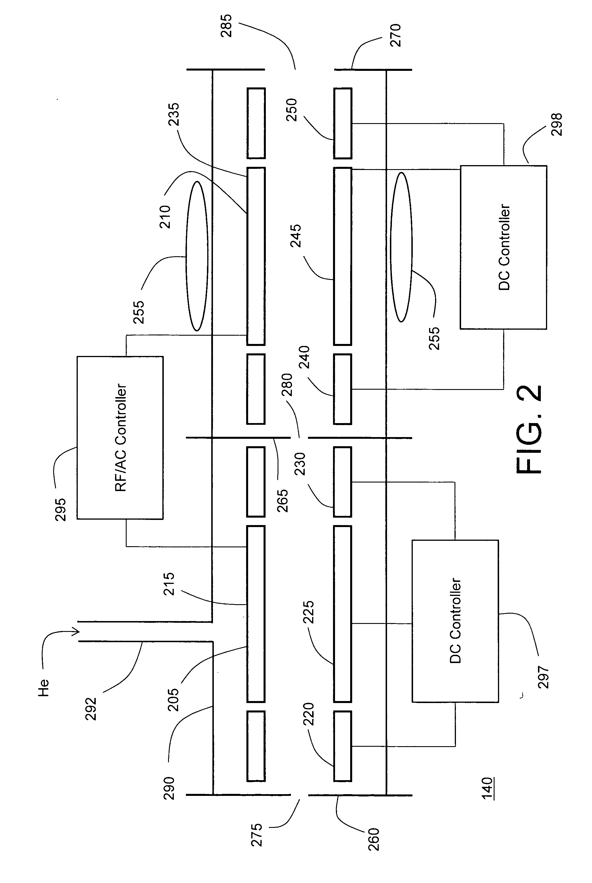
FIELD OF THE INVENTION[0001]The present invention relates generally to mass spectrometers, and more specifically to a differential-pressure, two-dimensional dual ion trap mass analyzer for use in a mass spectrometer system.BACKGROUND OF THE INVENTION[0002]The two-dimensional quadrupole ion trap mass analyzer (also referred to as the linear ion trap) is well known in the mass spectrometry art, and has become a valuable and widely-used tool for the analysis of a variety of compounds. Generally described, a two-dimensional ion trap consists of a set of four elongated electrodes to which a radio-frequency (RF) trapping voltage is applied in a prescribed phase relationship to radially confine ions to the trap interior. Axial confinement of the ions may be effected by application of a suitable direct current (DC) offset to end sections of the rod electrodes and / or electrodes located longitudinally outward of the rod electrodes. The mass spectrum of the trapped ions may be acquired by mass...

Claims


Application Information

Patent Timeline
Patent Type & Authority Applications(United States)
IPC IPC(8): H01J49/26
CPCH01J49/0045H01J49/4225H01J49/0418H01J49/0404
Inventor SCHWARTZ, JAE C.SYKA, JOHN E.P.QUARMBY, SCOTT T.
Owner THERMO FINNIGAN
Learn More