Pyrolyzer furnace apparatus and method for operation thereof

a technology of pyrolysis furnace and furnace, which is applied in the direction of lighting and heating apparatus, combustion types, incinerator apparatus, etc., can solve the problems of reducing increasing the energy consumption of pyrolysis furnaces, and shortened the life of furnace components, so as to reduce the external energy and reduce the level of additional energy

Inactive Publication Date: 2008-06-26
NUCOR CORP
View PDF80 Cites 66 Cited by
  • Summary
  • Abstract
  • Description
  • Claims
  • Application Information

AI Technical Summary

Benefits of technology

[0006]What has been needed is a pyrolyzer furnace system, and method for making char in that system, that substantially reduces the external energy, e.g. propane, fuel oil, or natural gas, needed for the char making process. The level of additional energy may be reduced to a point that the char making process is sustained by burning only the fluidized volatile materials generated from char making after start up.

Problems solved by technology

Previous pyrolyzer furnaces disclosed by the prior art had heating elements positioned within the furnace housing, which generated hot spots within the furnace, caused uneven heating of the coal or other carbon-bearing material, and caused fatigue and shortened the life of the furnace components.
Another limitation has been the energy efficiency of previous pyrolyzer furnaces.
Pyrolyzer furnaces in the prior art also had drive screws with solid shafts, oil cooled shafts, and other shaft configurations that were thermally inefficient, resulting in the pyrolyzer furnace consuming more fuel.

Method used


Image

  • Pyrolyzer furnace apparatus and method for operation thereof
  • Pyrolyzer furnace apparatus and method for operation thereof
  • Pyrolyzer furnace apparatus and method for operation thereof

Examples


Embodiment Construction

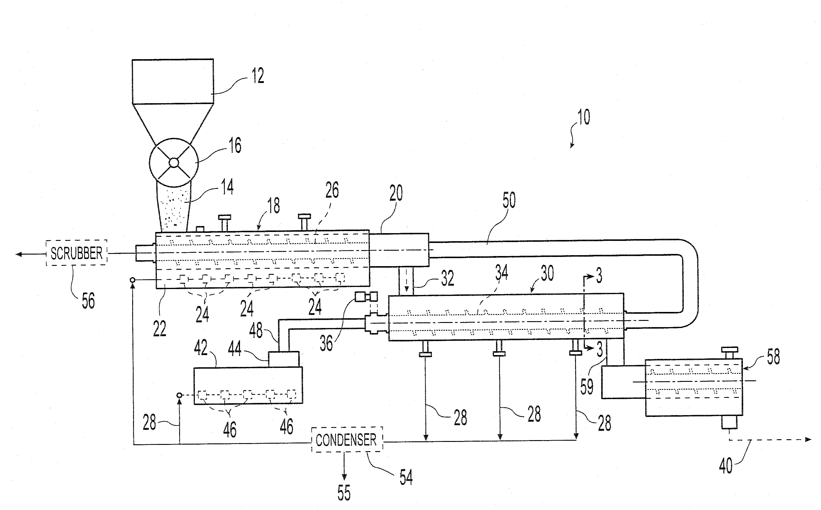
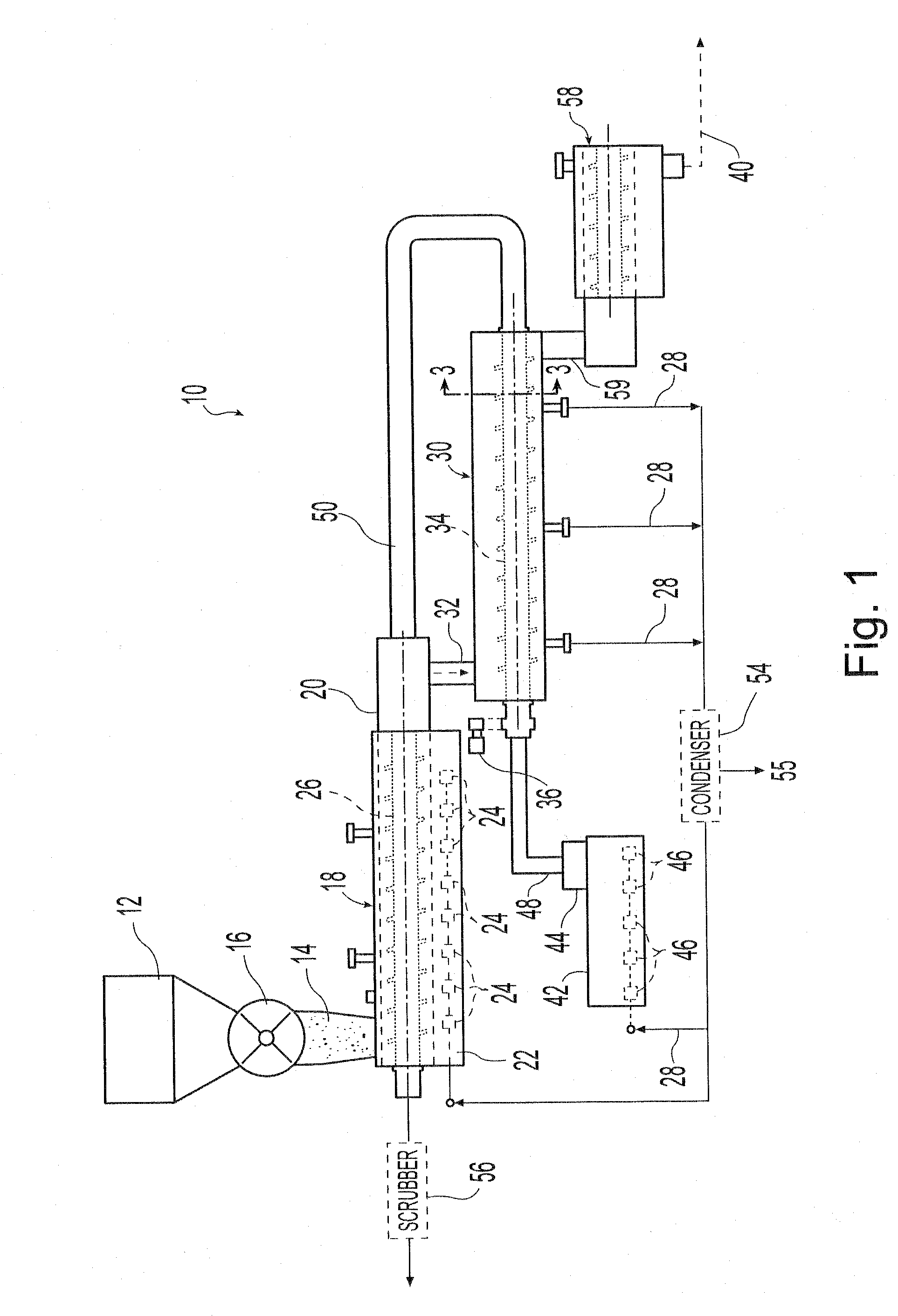
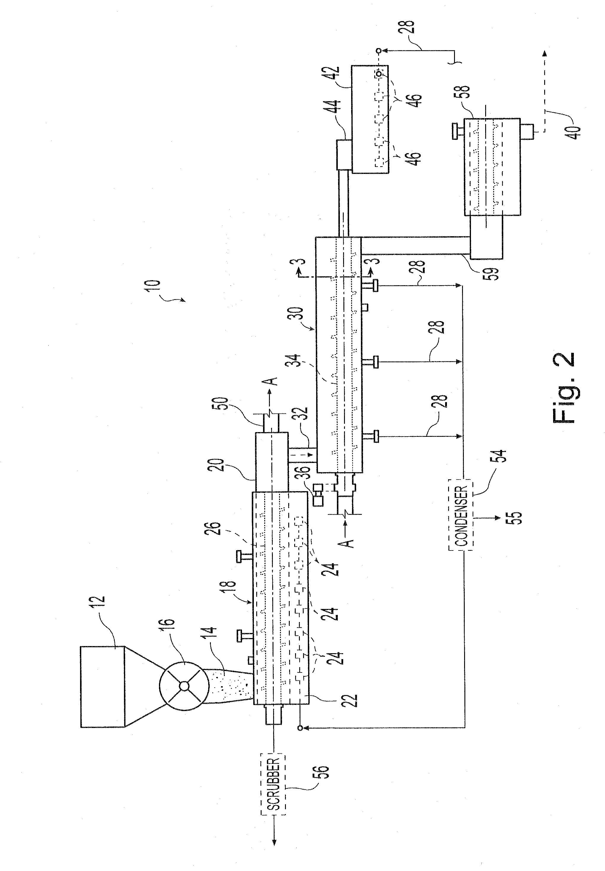
[0040]Referring now to FIG. 1, a furnace system 10 is provided for making char. The furnace system 10 receives, as raw materials, carbon-bearing material having a predetermined size, and processes the carbonaceous material into an atmosphere containing little, if any, oxygen. In the furnace, the carbon-bearing material is dried and then heated to a temperature to fluidize the volatile materials in the carbon-bearing material.

[0041]The furnace system 10 comprises a receiving hopper 12 for containing coal particles 14, or particles of other carbon-bearing materials, of a predetermined size. The size of the coal particles 14 may be, for example, in a range of about ¼ inch to about −6 Tyler mesh (about 6.4 mm to about 3.3 mm). The coal particles 14 pass from the receiving hopper 12 through an airlock 16 and into a pre-dryer 18.

[0042]The pre-dryer 18 comprises a drying chamber 20 within a drying furnace 22 having a plurality of burners 24 mounted therein. The drying chamber 20 has a driv...


PUM

PropertyMeasurementUnit
Reynolds numberaaaaaaaaaa
temperatureaaaaaaaaaa
Reynolds Numberaaaaaaaaaa

Abstract

A pyrolyzer and method is provided for devolatizing coal and other volatile materials. The pyrolyzer has a pyrolyzer furnace housing having at least two screws laterally positioned adjacent and overlapping rotatably mounted within the furnace for moving volatile material through the pyrolyzer furnace housing. The screws have hollow drive shafts with a diverter inside for converging heated fluid to heat the volatile material moving through the pyrolyzer furnace housing. A combustion chamber combusts fuel to create heated exhaust gas for directing through the hollow drive shafts to heat the volatile material. The pyrolyzer furnace housing may have a double wall with a cavity between, capable of receiving heated fluid for further heating of volatile material moving through the pyrolyzer furnace housing.

Description

[0001]This application claims the benefit of U.S. Provisional Patent Application 60 / 871,863 filed Dec. 26, 2006, incorporated herein by reference in its entirety.BACKGROUND AND SUMMARY OF THE DISCLOSURE[0002]The present invention relates to processing methods and apparatus for converting coal or other carbon-bearing materials into char. Char can be produced by heating coal or other carbon-bearing materials to selected temperatures in a reduced-oxygen environment. Char having suitable properties may be used in, among other things, iron and steel processing furnaces.[0003]Heating coal or other carbon-bearing materials in a reduced-oxygen environment produces coal gas, volatile liquids and a residue of char. During the process of making char, volatile materials, such as hydrocarbon fuels, in the carbon-bearing materials fluidize when heated to a temperature of approximately 650° F. (approximately 350° C.) and higher.[0004]A pyrolyzer furnace is one apparatus that may be used for proces...

Claims


Application Information

Patent Timeline
Patent Type & Authority Applications(United States)
IPC IPC(8): C10B47/44F23D1/02C10B7/10
CPCC10B47/44C10J3/007C10J2200/156C10J2300/0909C10J2300/093F23G2203/8013C10J2300/1207C10J2300/1223C10J2300/1246F23G5/0273F23G2201/303C10J2300/0973
Inventor WOLFE, RICHARD A.
Owner NUCOR CORP
Why Eureka
Try Eureka