Techniques for providing a ribbon-shaped gas cluster ion beam

a ribbon-shaped technology, applied in the field of ribbon-shaped gas cluster ion beams, can solve the problems of ineffective limited gas cluster ion beam implantation to the use of spot beams, and ineffective large-wavelet ion beams

Active Publication Date: 2008-06-26
VARIAN SEMICON EQUIP ASSOC INC
View PDF24 Cites 57 Cited by
  • Summary
  • Abstract
  • Description
  • Claims
  • Application Information

AI Technical Summary

Problems solved by technology

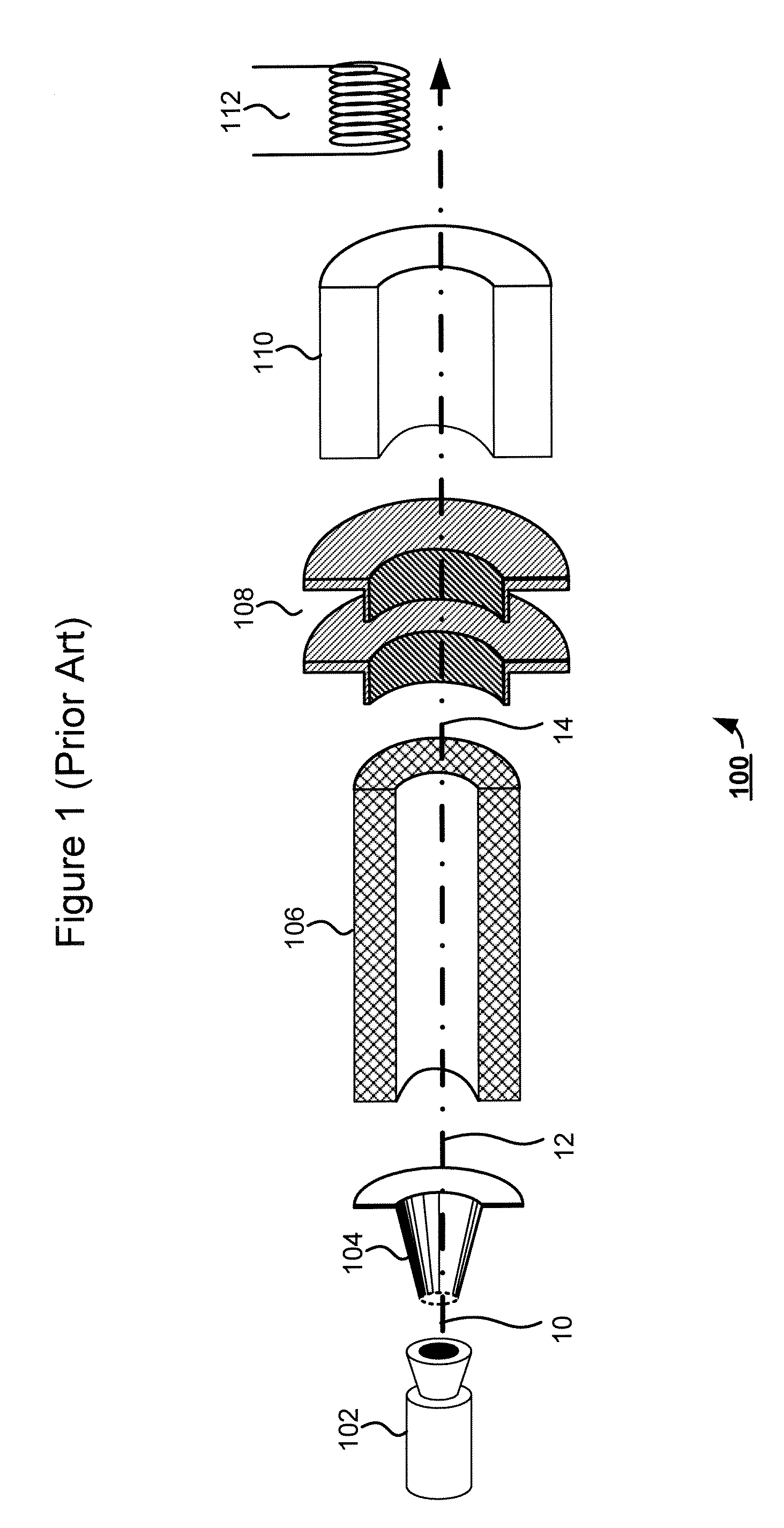
However, due to fundamental limitations in the extraction and transport of low-energy ions, conventional ion implantation systems may not perform satisfactorily to form shallow or ultra-shallow junctions.
So far, however, gas cluster ion implantation has been limited to the use of spot beams of gas clusters.
To use a single spot beam in a uniform implantation, the spot beam has to be scanned multiple times across an entire wafer, which may not be efficient for large wafers (which may be up to 300 mm in diameter these days).
In addition, the use of spot beams requires a complex design of end stations in order to accommodate two-dimensional wafer movements.

Method used


Image

  • Techniques for providing a ribbon-shaped gas cluster ion beam
  • Techniques for providing a ribbon-shaped gas cluster ion beam
  • Techniques for providing a ribbon-shaped gas cluster ion beam

Examples


Embodiment Construction

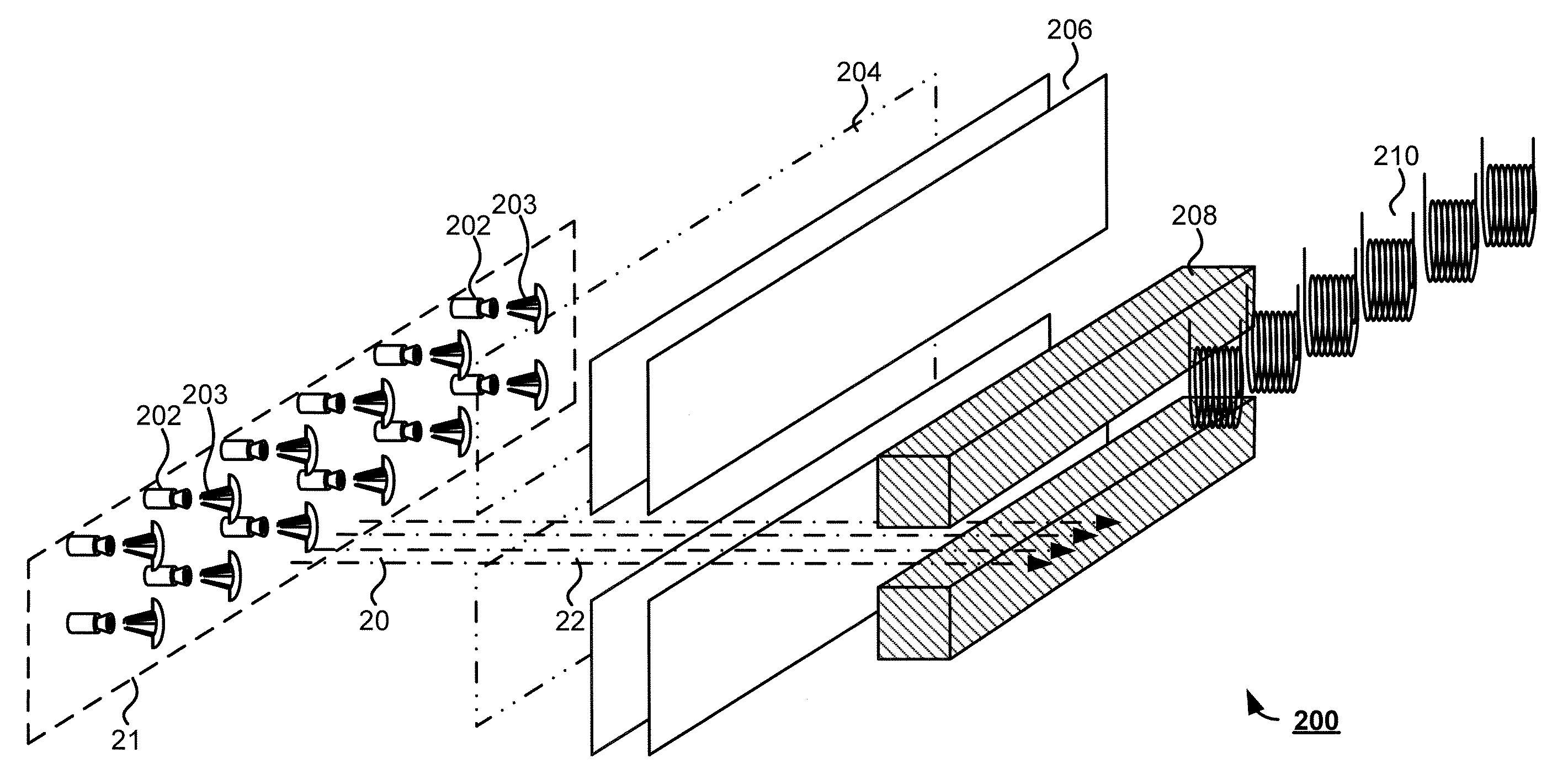
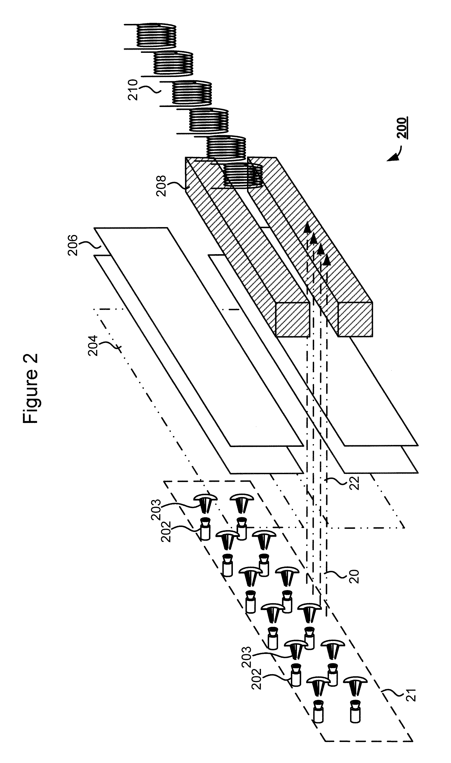
[0021]Referring to FIG. 2, there is shown an exemplary system 200 for generating a static ribbon-shaped gas cluster ion beam in accordance with an embodiment of the present disclosure. The system 200 may be enclosed in a vacuum chamber (not shown). The system 200 may comprise a plurality of nozzle-skimmer pairs that are arranged in an array 21 having a desired geometry. Each nozzle 202 may be capable of injecting a source gas at a sufficiently high speed (e.g., supersonic speed). The source gas may comprise any of a variety of gases, such as, for example, inert gases (e.g., argon), oxygen-containing gases (e.g., oxygen and carbon dioxide), nitrogen-containing gases (e.g., nitrogen), and other dopant-containing gases (e.g., diborane). The source gas may also be provided by heating up one or more solid substances until they vaporize. Upon injection into the vacuum chamber, the source gas may quickly expand, cool, and condense into a jet of gas clusters near each nozzle. As used herein...


PUM


Abstract

Techniques for providing a ribbon-shaped gas cluster ion beam are disclosed. In one particular exemplary embodiment, the techniques may be realized as an apparatus for providing a ribbon-shaped gas cluster ion beam. The apparatus may comprise at least one nozzle configured to inject a source gas at a sufficient speed into a low-pressure vacuum space to form gas clusters. The apparatus may also comprise at least one ionizer that causes at least a portion of the gas clusters to be ionized. The apparatus may further comprise a beam-shaping mechanism that forms a ribbon-shaped gas cluster ion beam based on the ionized gas clusters.

Description

FIELD OF THE DISCLOSURE[0001]The present disclosure relates generally to semiconductor manufacturing equipment and, more particularly, to techniques for providing a ribbon-shaped gas cluster ion beam.BACKGROUND OF THE DISCLOSURE[0002]Traditional ion implantation is a process of depositing chemical species into a substrate by direct bombardment of the substrate with energized ions. In semiconductor manufacturing, ion implanters are used primarily for doping processes that alter the type and level of conductivity of target materials. A precise doping profile in an integrated circuit (IC) substrate and its thin-film structure is often crucial for proper IC performance. To achieve a desired doping profile, one or more ion species may be implanted in different doses and at different energy levels.[0003]There has been a continuing effort to shrink feature sizes of semiconductor devices. As semiconductor devices are scaled down in size, the depth of related P-N junctions must be reduced ac...

Claims


Application Information

Patent Timeline
Patent Type & Authority Applications(United States)
IPC IPC(8): H01J27/02H01J27/08
CPCH01J27/026H01J37/08H01J2237/15H01J2237/006H01J2237/0812H01J37/3171
Inventor RENAU, ANTHONYOLSON, JOSEPH C.ENGLAND, JONATHAN GERALD
Owner VARIAN SEMICON EQUIP ASSOC INC
Why Eureka
Try Eureka