Radar device

a technology of a radar and a detector is applied in the field of radar devices, which can solve the problems of limiting the detection of reflected light with a low brightness, the variety of reflectivity of objects and their distances is quite large, and the saturation of the measured value of the photodiode, etc., and achieves the effect of simple structure and high level of accuracy

Inactive Publication Date: 2008-07-03
ORMON CORP
View PDF8 Cites 7 Cited by
  • Summary
  • Abstract
  • Description
  • Claims
  • Application Information

AI Technical Summary

Benefits of technology

[0009]It is therefore an object of this invention to provide a radar device with a simple structure capable of measuring the position of an object with a high level of accuracy even in an environment where the dynamic range of the incident light is wide.

Problems solved by technology

Since the background light and the diode noise are also amplified in this case, however, there has been a limit to the detection of reflected light with a low brightness.
In the outdoor environment in which a radar device of this type is used, however, the variety in the reflectivity of objects and their distances is quite large.
PIN photodiodes and avalanche photodiodes have the problem of saturation of the measured value when a large quantity of light flux in excess of its detection limit is received.
Thus, if light receiving sensitivity of the light receiving element is increased in order to detect reflected light with a low brightness outdoors where the dynamic range of the incident light is extremely wide as explained above, reflected light with a high brightness cannot be detected accurately and this causes a drop in the accuracy of measurement of a distance.
If a diaphragm is added to a lens for reducing the quantity of light flux entering the photodiode, the problem of saturation can be solved but it becomes difficult to detect reflected light with a low brightness.
If the bias voltage applied to an avalanche photodiode is reduced, the light receiving sensitivity of the avalanche photodiode itself becomes controlled and the problem of saturation of the received light can be eliminated but the parasitic capacitance of the avalanche photodiode itself increases rapidly and the response to high-speed signals becomes poorer and the distance-measuring capability is adversely affected.

Method used


Image

  • Radar device
  • Radar device
  • Radar device

Examples


Embodiment Construction

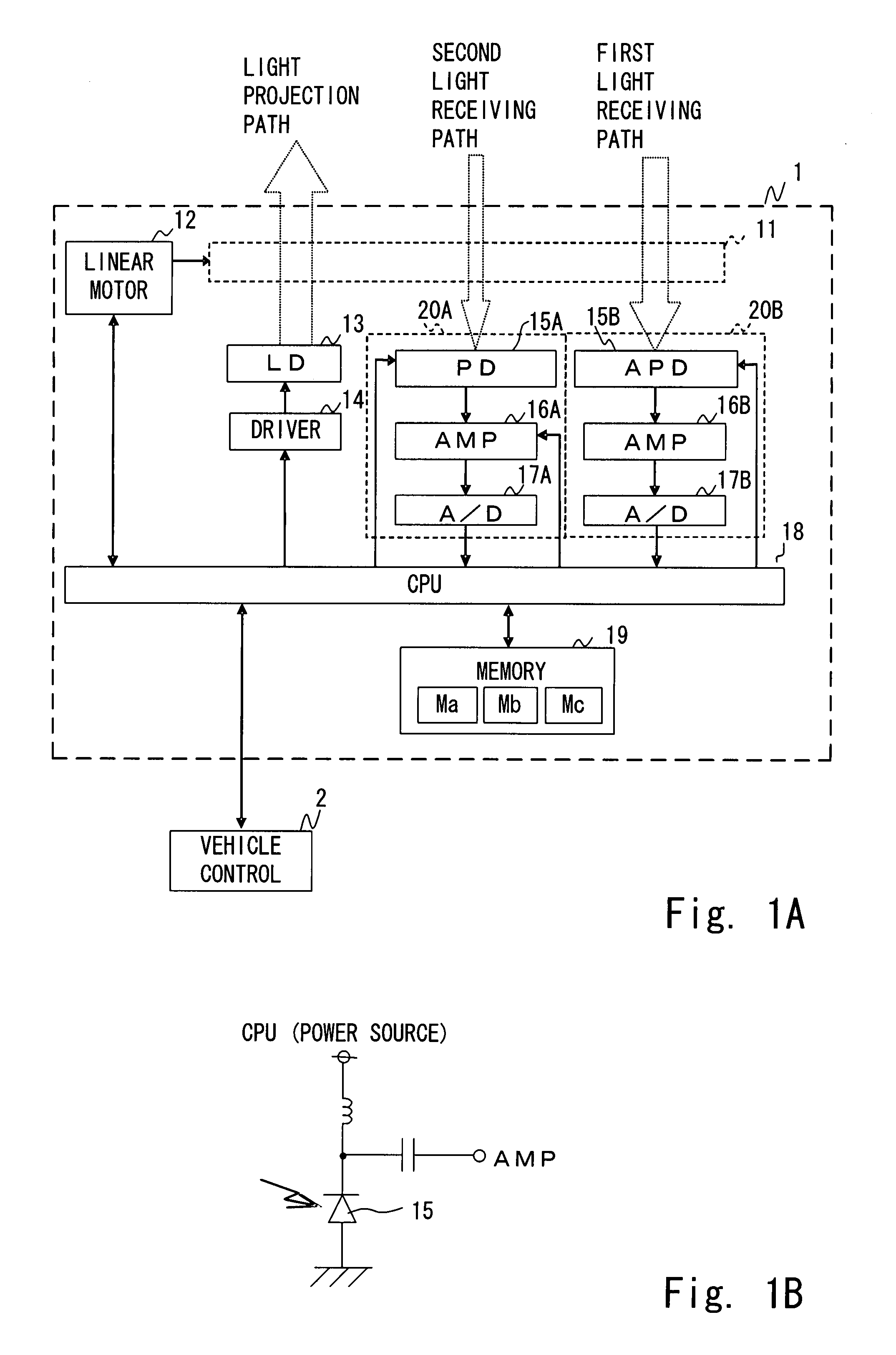
[0035]The invention is described next with reference to drawings. FIG. 1A is a block diagram of a radar device 1 comprising an optical unit 11, a linear motor 12, a laser diode (LD) 13, a driver 14, light receiving circuits 20A and 20B, a CPU 18 and a memory 19.

[0036]The optical unit 11 has a light projecting path, a first light receiving path and a second light receiving path. The first and second light projecting paths serve to guide light flux from the direction of an object respectively to an avalanche photodiode (APD) 15B and a photodiode (PD) 15A.

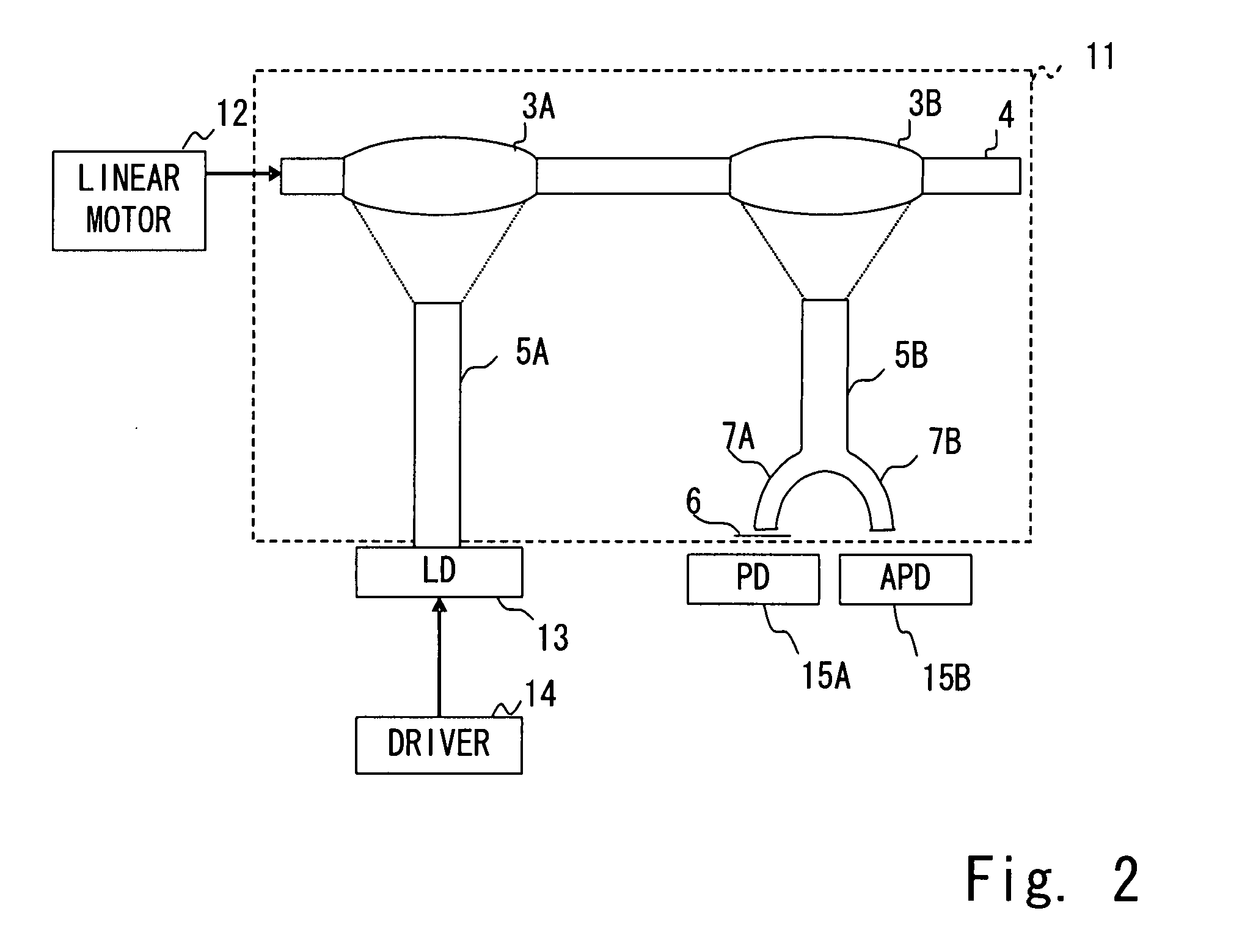
[0037]As shown in detail in FIG. 2, the optical unit 11 is provided with a light projecting lens 3A, a light receiving lens 3B, a lens frame 4 that connects these lenses, a light guide 5A having a light projecting surface at the position of the focus of the light projecting lens 3A, another light guide 5B which is a branched light guide serving to branch received light flux evenly into its two branches 7A and 7B and having a light rec...


PUM


Abstract

A radar device includes a light projecting part for projecting light to an object, first and second light receiving elements each for outputting a signal according to the quantity of received light flux, and an optical system having a first optical path and a second optical path for guiding reflected light from the object respectively to the first light receiving element and to the second light receiving element. The optical system guides more light flux to the first optical path than to the second optical path corresponding to an incident light flux to the radar device.

Description

[0001]This application claims priority on Japanese Patent Application 2006-189641 filed Jul. 10, 2006.BACKGROUND OF THE INVENTION[0002]This invention relates to a radar device for measuring the distance to an object outdoors by irradiating near-infrared light or the like to it by using a laser diode and receiving reflected light therefrom through an optical system by using photodiodes.[0003]Distance-measuring apparatus using a radar device for scanning the front outdoors with a laser beam of near-infrared light or the like to detect the presence or absence of an object in front (such as a front-going vehicle, an obstacle or a pedestrian in the case of a vehicle-mounted radar device) from the incident light including reflected light as well as the distance to a detected object have been coming to be popularly used. Conventional radar devices have been for causing a near-infrared light beam emitted from a laser diode to be reflected from an object, leading the reflected light through ...

Claims


Application Information

Patent Timeline
Patent Type & Authority Applications(United States)
IPC IPC(8): G01S13/00
CPCG01S7/4811G01S7/4816G01S17/08G01S7/497G01S7/4818
Inventor ISHIO, WATARUFUJIOKA, RYOJIMORIKAWA, YUICHI
Owner ORMON CORP
Why Eureka
Try Eureka