Method for Manufacturing Semiconductor Device
a semiconductor and manufacturing method technology, applied in semiconductor/solid-state device testing/measurement, instruments, printing, etc., can solve the problems of high processing accuracy, difficult to understand circuit structure or wiring arrangement, and difficult to design complex integrated circuits, so as to achieve the effect of increasing the kinds of materials which can be used for manufacturing semiconductor devices and efficient use of materials
- Summary
- Abstract
- Description
- Claims
- Application Information
AI Technical Summary
Benefits of technology
Problems solved by technology
Method used
Image
Examples
embodiment mode 1
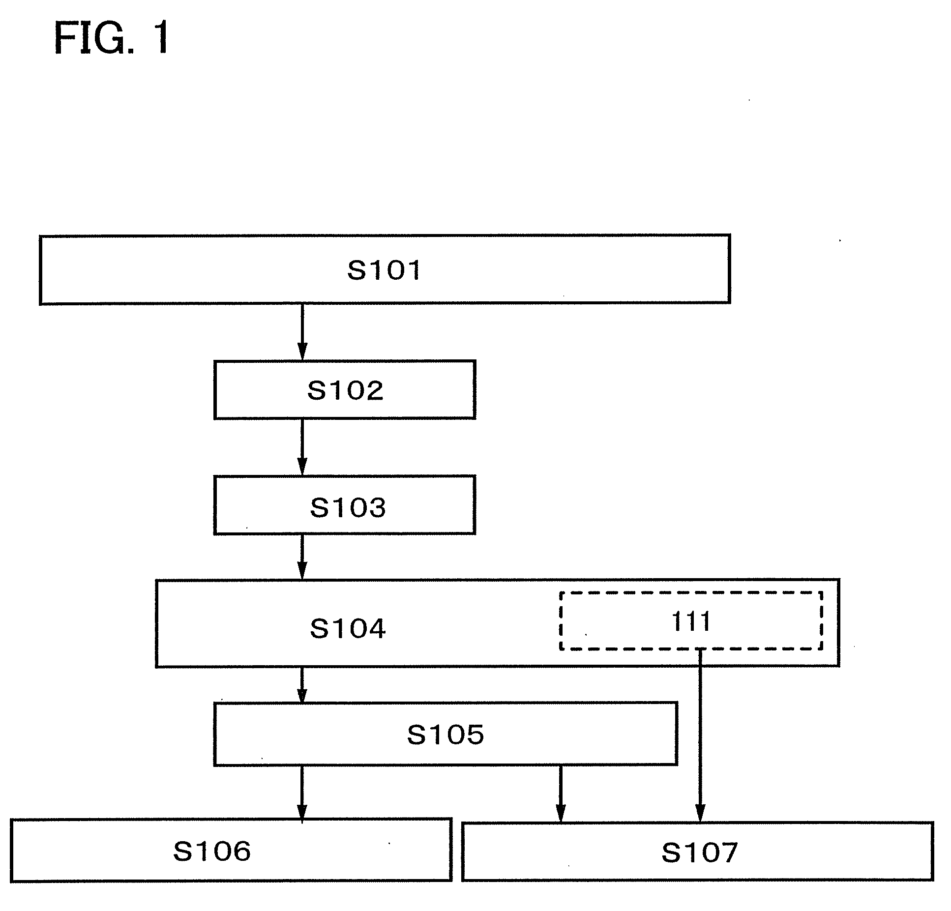
[0051]In this embodiment mode, procedures of manufacturing a mask and making raster data will be explained with reference to FIG. 1.
[0052]First, a droplet is discharged over a surface to be processed by a droplet discharging apparatus, and measurement of a diameter d of the droplet landed is performed (S101). By measurement of the diameter d of the droplet, a design unit of the mask and the raster data is determined.
[0053]Next, coordinates are made regarding a size of greater than or equal to 50% and less than 90% of the diameter d of the droplet as one unit (S102). Here, this one unit is referred to as a dot pitch, and each block of the coordinates is a square element having a dot pitch dpx (a main scanning direction)×a dot pitch dpy (a sub scanning direction). However, one element of the coordinates is not limited to a square and may have a rectangle where dpx≠dpy.
[0054]Next, a circuit is designed in order to determine arrangement or the like of a wiring to be obtained using a dro...
embodiment mode 2
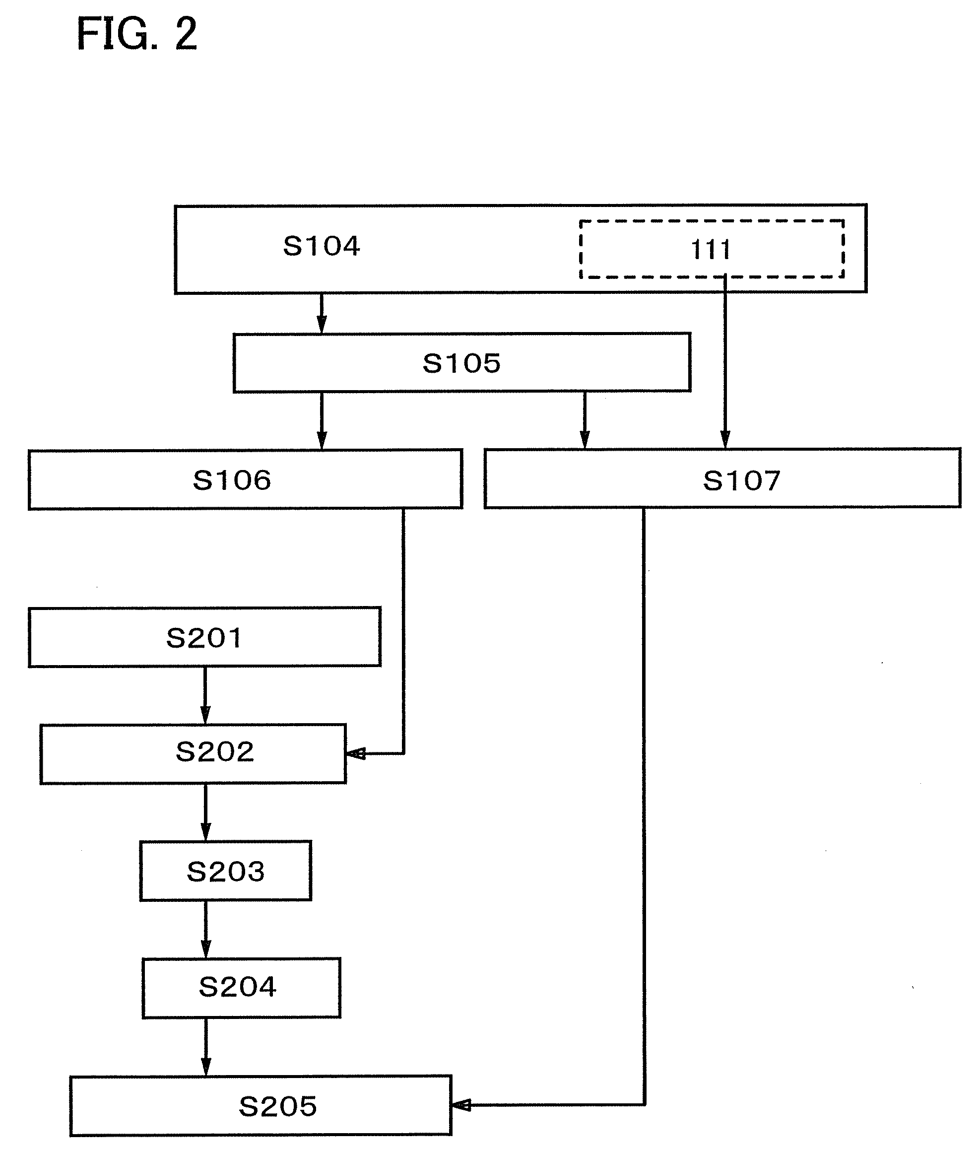
[0062]Here, flow until a droplet of a conductive material is discharged over a surface to be processed will be explained with reference to FIG. 2. Note that the same reference numerals are used for parts which are in common with FIG. 1. A method for forming a wiring mainly containing silver by discharging a droplet including silver nanoparticle over the surface to be processed of a glass substrate will be explained hereinafter.
[0063]First, a resist is applied over the surface to be processed (S201). As a resist material, a positive type resist or a negative type resist is used. Here, a glass substrate of which surface to be processed is formed of an inorganic material is used. In order to improve adhesiveness with the silver nanoparticle, the negative type resist is used.
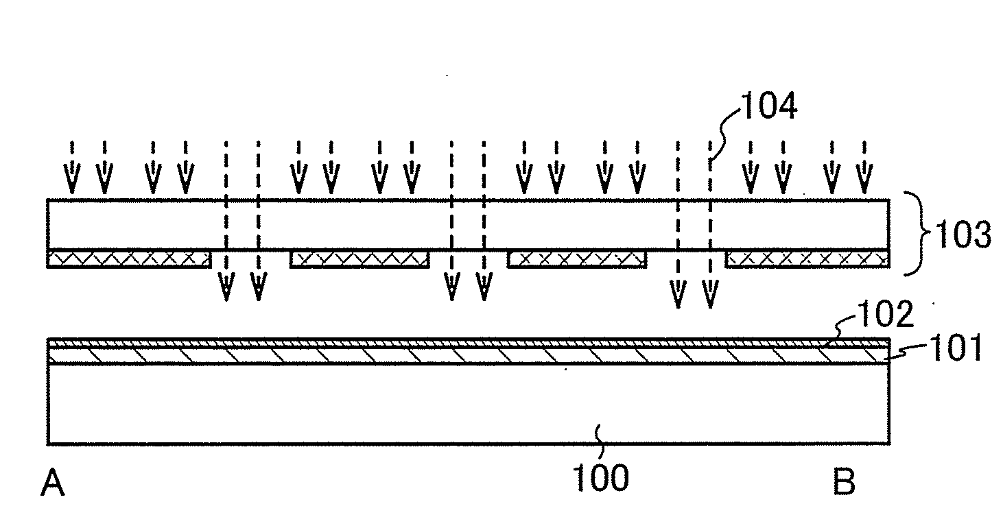
[0064]Next, light exposure is performed using the mask formed in Embodiment Mode 1 as a light-exposure mask (S202). FIG. 4A shows an example of a layout of the mask. The light-exposure mask is a light shielding mask...
embodiment mode 3
[0075]Here, examples of a mask design diagram and examples of raster data in which block patterns different from those shown in FIG. 4 are used will be described with reference to FIG. 5A to FIG. 6B.
[0076]FIG. 5A is a mask design diagram which is made using three kinds of block patterns B1, C1, D1 selected from the diagram registering library.
[0077]FIG. 5A is the mask design diagram when a source wiring and a drain electrode of a thin film transistor are formed with the ink-jet apparatus. A light shielding mask which has openings in places shown by shaded portions 501 in FIG. 5A is made.
[0078]FIG. 5B shows an example of the raster data corresponding to FIG. 5A. Discharging is performed the same number of times (20) as the number of patterns to the places corresponding to the block pattern D1. Discharging is performed once for three continuous pitches to the places corresponding to the block pattern C1. Further, the most suitable pitches in the Y direction, that is, in the scanning d...
PUM
 Abstract
Description
Claims
Application Information
 - R&D
- Intellectual Property
- Life Sciences
- Materials
- Tech Scout
- Unparalleled Data Quality
- Higher Quality Content
- 60% Fewer Hallucinations
Browse by: Latest US Patents, China's latest patents, Technical Efficacy Thesaurus, Application Domain, Technology Topic, Popular Technical Reports.
© 2025 PatSnap. All rights reserved.Legal|Privacy policy|Modern Slavery Act Transparency Statement|Sitemap|About US| Contact US: help@patsnap.com


