Ion beam monitoring arrangement

a technology of ion beam and monitoring arrangement, which is applied in the field of ion beam monitoring arrangement, can solve the problems of negative residual positive charge, space-charge blow-up of ion beam, accumulation of charge, etc., and achieve the effect of improving ion beam neutrality

Inactive Publication Date: 2008-07-17
APPLIED MATERIALS INC
View PDF3 Cites 5 Cited by
  • Summary
  • Abstract
  • Description
  • Claims
  • Application Information

AI Technical Summary

Benefits of technology

[0025]Such a method is advantageous as it allows measurements to be made of the floating potential part way through an implant. This allows corrections to be made, e.g. the ion beam may be adjusted or the operation of a plasma flood system may be adjusted to improve ion beam neutrality as measured by the device. Of course, such adjustments may still be made whenever measurements of the floating potential are made, and not just when they are made between scan lines. For example, measurements of the floating potential may be made between multiple passes over the substrate during an implant.

Problems solved by technology

Ion beams often have a residual positive charge that is detrimental for at least two reasons.
First, it causes space-charge blow-up of the ion beam, particularly at the substrate where the ion beam tends to be at its least energetic.
Second, the net positive charge in and around the ion beam seen at the plane of the substrate is transferred to the substrate during implantation, and this accumulation of charge can damage devices being fabricated on the substrate.
This is a particular problem in mechanically-scanned serial implanters where scan speeds are slow.
By the very nature of the test wafer, measurements cannot be made during an implant.
Clearly, this is a time-consuming process that reduces the throughput of processed wafers through the ion implanter.

Method used


Image

  • Ion beam monitoring arrangement
  • Ion beam monitoring arrangement
  • Ion beam monitoring arrangement

Examples


Embodiment Construction

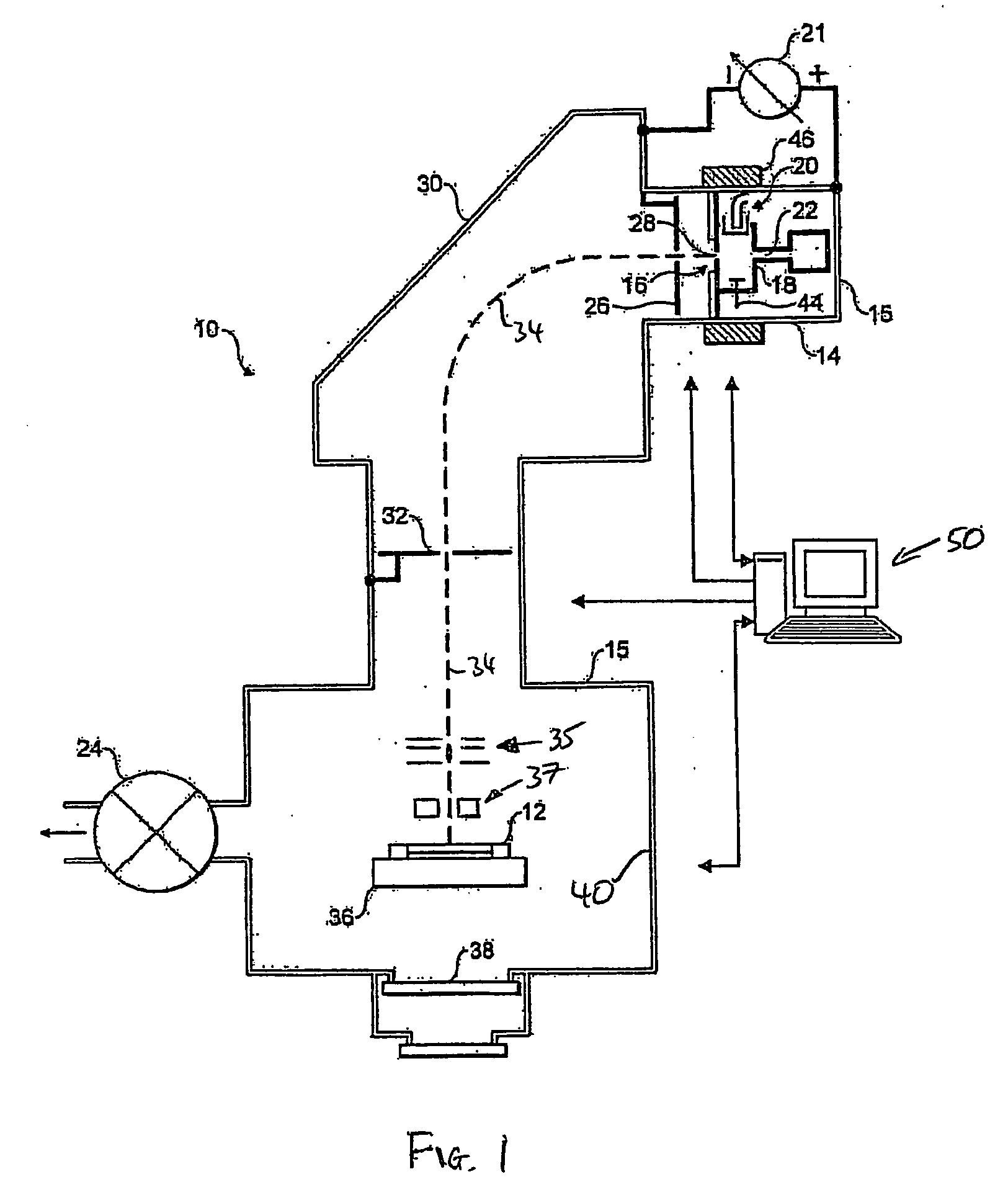
[0039]In order to provide a context for the present invention, an exemplary application is shown in FIG. 1, although it will be appreciated that this is merely an example of an application of the present invention and is in no way limiting.

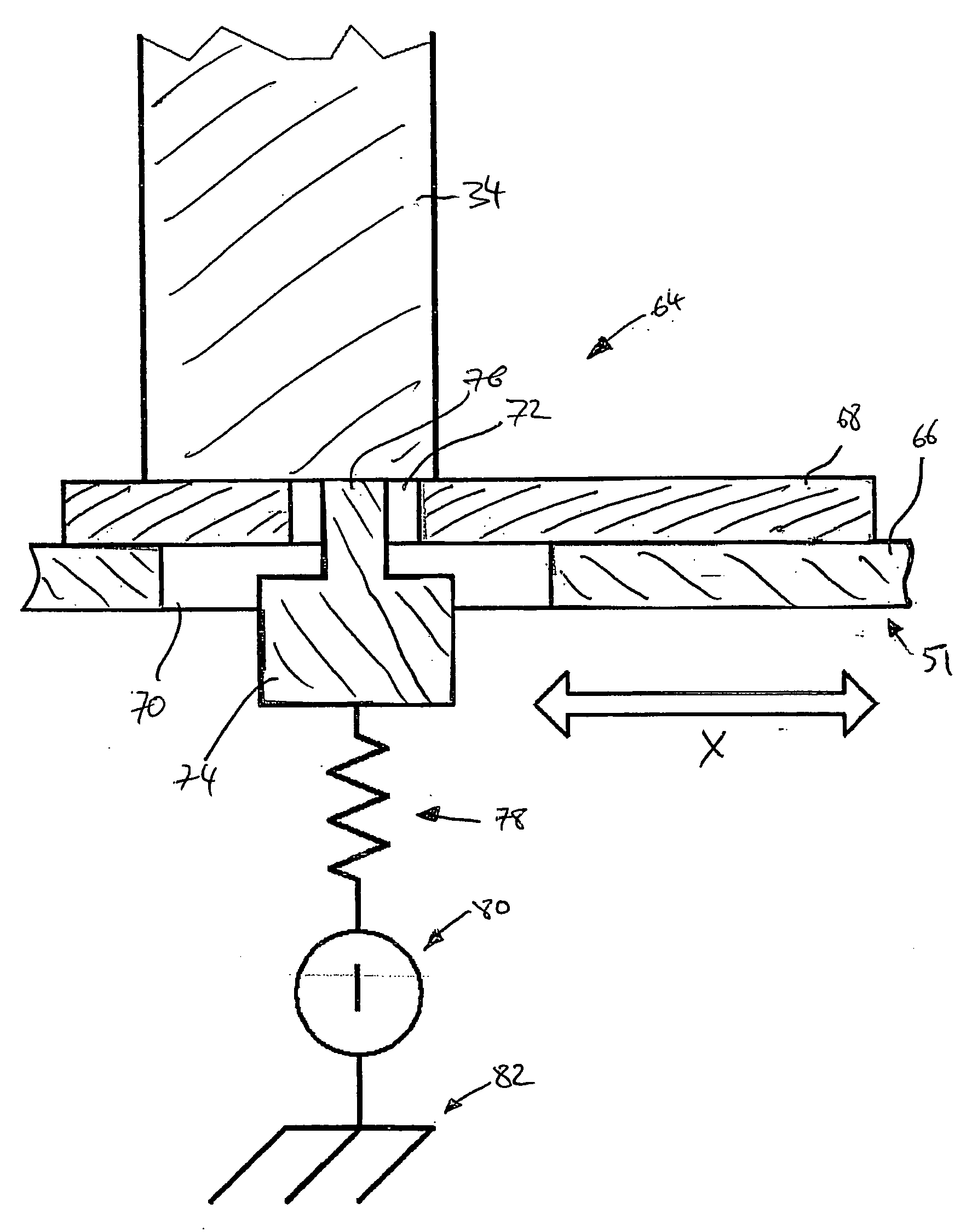
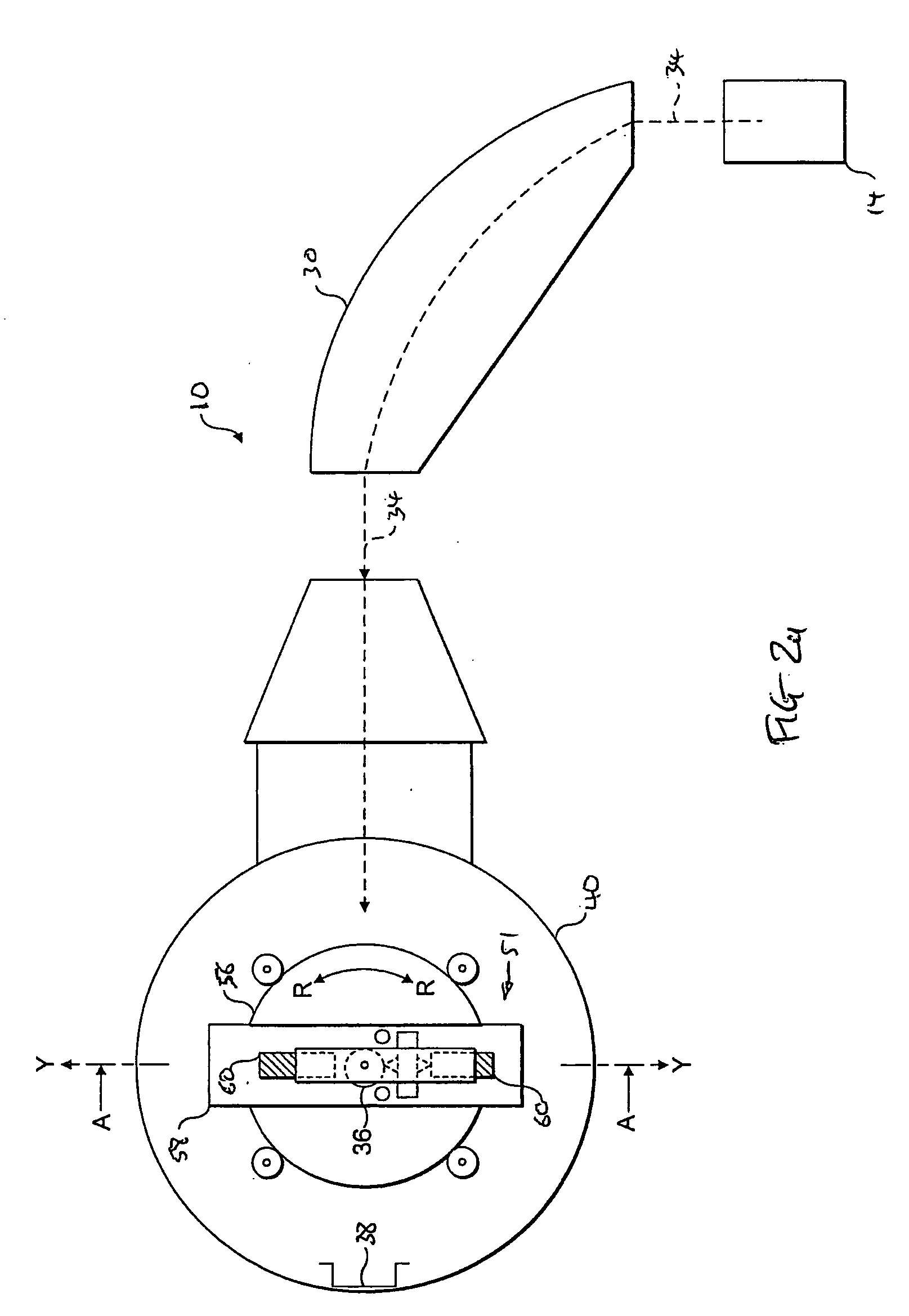
[0040]FIG. 1 shows a known ion implanter 10 for implanting ions in semiconductor wafers 12. Ions are generated by the ion source 14 to be extracted and follow an ion path 34 that passes, in this embodiment, through a mass analysis stage 30. Ions of a desired mass are selected to pass through a mass-resolving slit 32 and carry on eventually to strike the semiconductor wafer 12.

[0041]The ion implanter 10 contains an ion source 14 for generating an ion beam of a desired species that is located within a vacuum chamber 15 evacuated by pump 24. The ion source 14 generally comprises an arc chamber 16 containing a cathode 20 located at one end thereof. The ion source 14 may be operated such that an anode is provided by the walls 18 of the arc chamber 16. ...


PUM


Abstract

This invention relates to an ion beam monitoring arrangement for use in an ion implanter where it is desirable to monitor the floating potential across an ion beam used for implantation. The invention provides a ion beam monitoring arrangement comprising a device configured to measure the floating potential of an ion beam when incident thereon, wherein the device is coupled to a substrate support so as to face outwardly in a position so as not to be obscured by a substrate of the contemplated size when held by the substrate holder. Thus, measurements of the floating potential may be taken with a substrate held in place. The ion beam monitoring arrangement may be used to move the device into the ion beam in much the same way as it used to scan a substrate through the ion beam.

Description

FIELD OF THE INVENTION[0001]This invention relates to an ion beam monitoring arrangement for use in an ion implanter where it is desirable to monitor the floating potential across an ion beam used for implantation. This invention also relates to an ion implanter including such a ion beam monitoring arrangement, and to methods of measuring the floating potential of an ion beam and of implanting a substrate.[0002]In particular, the present invention relates to measuring the floating potential in and around an ion beam at or close to the plane of a substrate being implanted so as to be able to control the ion beam to minimise charge accumulation caused by the ion beam. This may be performed through ion beam tuning and / or a plasma flood system.BACKGROUND OF THE INVENTION[0003]Ion implanters are well known and generally conform to a common design as follows. An ion source produces a mixed beam of ions from a precursor gas or the like. Only ions of a particular species are usually require...

Claims


Application Information

Patent Timeline
Patent Type & Authority Applications(United States)
IPC IPC(8): G21K5/10G01R31/00G06F9/30
CPCH01J37/026H01J37/304H01J37/3171H01J2237/24507H01J2237/2008H01J2237/20228H01J2237/0044
Inventor SAKASE, TAKAOFARLEY, MARVINHAYS, STEVEN C.
Owner APPLIED MATERIALS INC
Why Eureka
Try Eureka