Catalytic membrane reactor and method for production of synthesis gas

a catalytic membrane reactor and catalyst technology, applied in the direction of combustible gas production, oxygen/ozone/oxide/hydroxide, chemical production, etc., can solve the problems of difficult to reform commercial diesel fuel into synthesis gas in small compact fuel reformers without greatly dropping the overall system efficiency, and the deposition of carbon is particularly problematic, so as to achieve the effect of high oxygen flux

Inactive Publication Date: 2008-07-17
ELTRON RES
View PDF6 Cites 131 Cited by
  • Summary
  • Abstract
  • Description
  • Claims
  • Application Information

AI Technical Summary

Benefits of technology

[0031]In some embodiments the metal oxide has the formula La1−xAxBO3−δ, wherein A=Ca2+ or Sr2+, B=Co, Mn, or Fe, x is greater than 0 and less than 1, and δ is the number of oxygen vacancies in the metal oxide crystal lattice. In some embodiments the membrane comprises a first section configured for surrounding a <900° C. zone in a fuel reforming reactor and a second

Problems solved by technology

A major impediment to the commercialization of solid oxide fuel cell systems for the automotive market is the lack of efficient, low-cost, compact reformers for carrying out the conversion of diesel fuel to synthesis gas.
Hitherto, it has proven difficult to reform commercial diesel fuel into synthesis gas in small compact fuel reformers without greatly dropping overall system efficiency by use of excess steam, hydrogen or oxygen to suppress formation of carbon.
Deposition of carbon is especially problematic in the range 300-800° C. where reaction kinetics favors rapid cracking of fuel into carbon.
A key issue in the design of a diesel fuel reformer is the prevention of the formation of elemental carbon.
If conditions are thermodynamically and kinetically favorable for the formation of graphite, carbon will readily deposit onto reactor walls and onto reformer catalysts, rapidly poisoning catalysts and plugging reactors.
However, those options lead to reduction of overall fuel cell system efficiencies.
A second major issue in reforming diesel fuel is the poisoning of most common reforming catalysts (e.g., those based upon nickel) by sulfur which is present in relatively large quantities in automotive fuels.
It has proven difficult to reform fuel containing

Method used


Image

  • Catalytic membrane reactor and method for production of synthesis gas
  • Catalytic membrane reactor and method for production of synthesis gas
  • Catalytic membrane reactor and method for production of synthesis gas

Examples


example 1

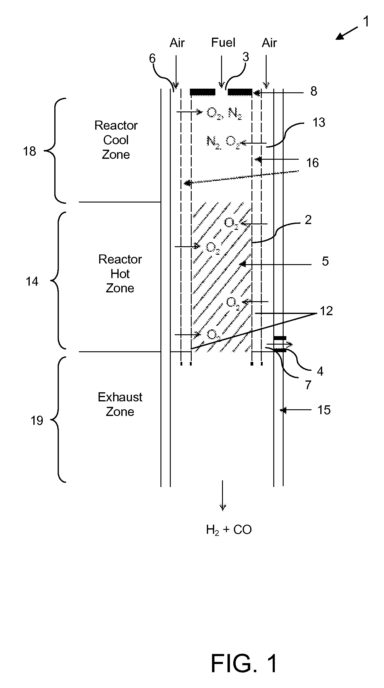
[0200]Porous wall of yttria stabilized zirconia (or other ceramic) is coated with perovskite oxidation catalysts, especially La1−xCaxFeO3−δ (or variations of this perovskite material, such as La1−xSrxFeO3-6, La1−xSrxCoO3−δ, La1−xCaxCoO3−δ, La1−xCaxMnO3-6, La1−xSrxMnO3−δ). La1−xCaxFeO3-6 and variations thereof are used as oxidation catalysts in the hot zone (1000° C.) of the reactor.

example 2

[0201]Porous wall of yttria stabilized zirconia is coated with Pt—Rh oxidation catalyst in the cool zone of the reactor (300-900° C.). Platinum-rhodium catalyst is dispersed within the pores of the ceramic reactor wall using electroless deposition. Wire Pt—Rh gauze is used as the oxidation catalyst in the hot zone of the reactor (>1000° C.).

example 3

[0202]Porous wall of yttria stabilized zirconia coated with perovskite oxidation catalyst such as La1−xCaxFeO3−δ and allied materials, is employed along with Pt—Rh gauze in the hot zone of the reactor.


PUM


Abstract

A solid state membrane for a reforming reactor is disclosed which comprises at least one oxygen anion-conducting oxide selected from the group consisting of hexaaluminates, cerates, perovskites, and other mixed metal oxides that are able to adsorb and dissociate molecular oxygen. The membrane adsorbs and dissociates molecular oxygen into highly active atomic oxygen and allows oxygen anions to diffuse through the membrane, to provide high local concentration of oxygen to deter formation and deposition of carbon on reformer walls. Embodiments of the membrane also have catalytic activity for reforming a hydrocarbon fuel to synthesis gas. Also disclosed are a reformer having an inner wall containing the new membrane, and a process of reforming a hydrocarbon feed, such as a high sulfur-containing diesel fuel, to produce synthesis gas, suitable for use in fuel cells.

Description

CROSS-REFERENCE TO RELATED APPLICATIONS[0001]This application claims the benefit under 35 U.S.C. § 119(e) of U.S. Provisional Patent Application No. 60 / 843,433 filed Sep. 8, 2006, the disclosure of which is hereby incorporated herein by reference.STATEMENT REGARDING FEDERALLY SPONSORED RESEARCH OR DEVELOPMENT[0002]The U.S. Government has a paid-up license in this invention and the right in limited circumstances to require the patent owner to license others on reasonable terms as provided for by the terms of Contract No. DE-FG02-05ER84394 awarded by the U.S. Department of Energy SBIR Program.BACKGROUND OF THE INVENTION[0003]1. Technical Field of the Invention[0004]The present disclosure generally relates to methods, compositions and apparatus for reforming carbonaceous feedstocks to produce synthesis gas. More particularly, this disclosure relates to the reforming of hydrocarbon fuels using a catalytic membrane reactor having walls that are catalytic and provide enhanced local concen...

Claims


Application Information

Patent Timeline
IPC IPC(8): C01B3/38C10J3/48C01B32/40
CPCB01D69/141B01D71/024C01B3/382C01B13/0255C01B2210/0046C01B2203/0244C01B2203/0261C01B2203/066C01B2203/1247C01B2203/0233Y02P20/52B01D71/0271
Inventor MUNDSCHAU, MICHAEL V.
Owner ELTRON RES
Why Eureka
Try Eureka