Field emission electron gun and method of operating the same

a field emission electron and electron gun technology, applied in the direction of discharge tube/lamp details, discharge tube main electrodes, incadescent cooling arrangements, etc., can solve the problems of localized change in work function, and fluctuation of field emission current, so as to achieve stable field emission current, low noise level, and high resolution

Inactive Publication Date: 2008-07-17
HITACHI HIGH-TECH CORP
View PDF3 Cites 7 Cited by
  • Summary
  • Abstract
  • Description
  • Claims
  • Application Information

AI Technical Summary

Benefits of technology

[0012]The present invention makes it possible to provide an electron gun capable of obtaining a stable field emission current constantly for a long period of time, and to control an energy distribution of the field emission electrons so as not to spread widely due to heating.
[0013]In addition, by applying an electron gun according to the present invention to electron-beam-applied apparatuses, for example, a scanning electron microscope (SEM) and an electron beam lithography, it is possible to provide the apparatuses which have a low noise level and a high resolution even while operated continuously for a long period of time.

Problems solved by technology

A chief cause of fluctuation in a field emission current is a localized change in the work function which takes place due to a repeated series of a residual gas's adsorption (contamination) to, and desorption from, a field emission site in the extremity of a carbon nanotube.
This brings about a problem that the field emission current fluctuates again.
In this case, it is impossible to completely remove the adsorbed gas only by heating the carbon nanotube electron source at a temperature of approximately 600K, and it is also impossible to obtain a stable field emission current without heating the carbon nanotube electron source at a temperature of not lower than 1000K once.
Moreover, when the heating temperature is raised unnecessarily, the energy distribution of the field emission electrons spreads, although the field emission current is stabilized.
This widely-spread energy distribution presents a cause of deteriorating the resolution of an electron microscope in a case where the carbon nanotube electron source is installed in the electron microscope.

Method used


Image

  • Field emission electron gun and method of operating the same
  • Field emission electron gun and method of operating the same
  • Field emission electron gun and method of operating the same

Examples


embodiment 1

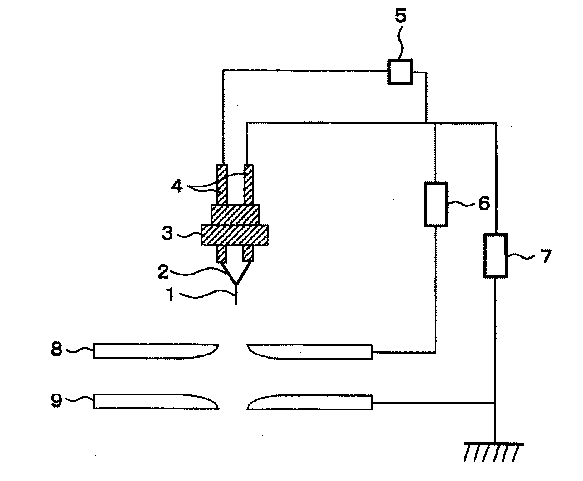
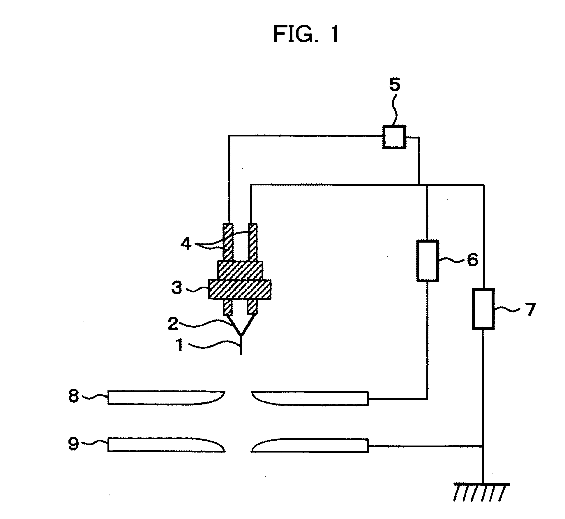
[0029]FIG. 1 shows a configuration of an electron gun according to a first embodiment. The electron source is configured of at least a carbon nanotube and a conductive base material supporting the carbon nanotube. The field emission electron gun includes: the electron source; an extracting electrode for causing electrons to be emitted; an accelerating electrode for accelerating the electrons; a drawer power supply for applying a voltage to the extracting electrode; an accelerating power supply for applying a voltage to the accelerating electrode; and a heating power supply for heating the electron source.

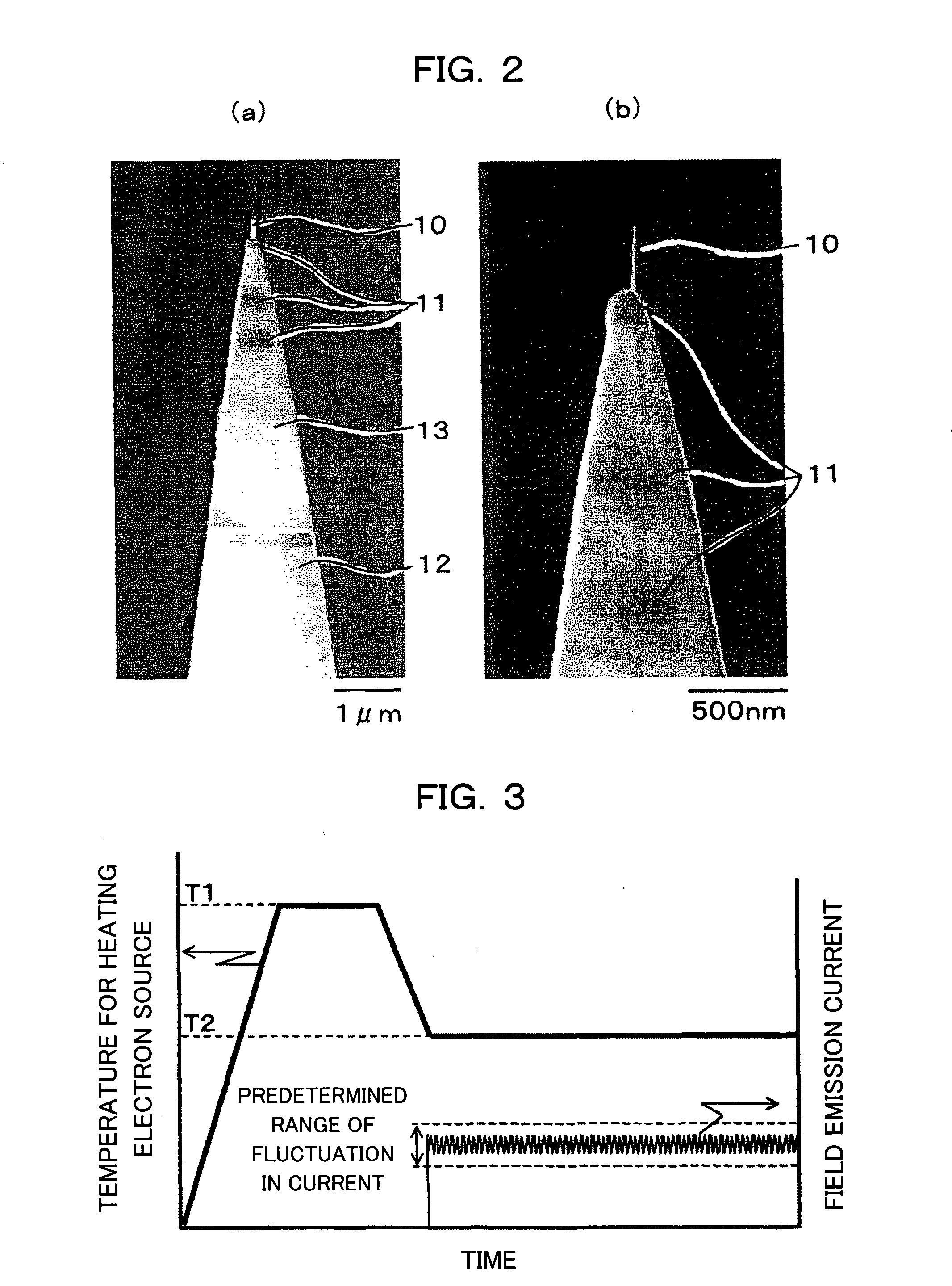
[0030]FIGS. 2A and 2B are SEM pictures of the extremity portion of the electron source according to this embodiment. The field emission electron source is configured of a single carbon nanotube, a conductive base material, a isolated supporting base for supporting the base material, and an electrode. A section where the carbon nanotube and the conductive base material are jointed to...

embodiment 2

[0040]FIGS. 6A and 6B respectively show examples of the electron gun according to the present invention. For the purpose of lowering the heating temperature as described above, this electron gun has a configuration in which a means for detecting the field emission current and a means for monitoring the field emission current are added to the electron gun shown in FIG. 1. It should be noted that the field emission current is capable of being detected by the extracting electrode (as shown in FIG. 6A) or the stop provided under the accelerating electrode (as shown in FIG. 6B).

[0041]The current fluctuation which takes place during field emission is beforehand examined, and an appropriate range of the current fluctuation is set. Thereby, the field emission current monitoring device constantly monitors whether or not the field emission current falls within a predetermined range of the current fluctuation. In addition, the heater is controlled in accordance with a result of the monitoring....

embodiment 3

[0045]FIG. 8 is a diagram showing an example of an overall configuration of a scanning electron microscope (SEM) to which the electron gun according to the present invention is applied.

[0046]In the scanning electron microscope, an alignment coil, a condenser lens, an astigmatic correction coil, a deflecting / scanning coil, an object lens and an object stop are arranged sequentially along an electron beam of emitted from the electron gun. A sample is placed on a sample stage, and the electron beam is emitted on the sample. A secondary electron detector is provided in a sidewall portion of a sample chamber. In addition, the sample chamber is designed to be held in high vacuum by a discharge system. With this configuration, the electron beam emitted from the electron gun is accelerated by an anode, and is condensed by the electron lens. Thereby, the resultant electron beam is emitted on a minute area on the sample. This irradiated area is scanned over two-dimensionally. Thereby, seconda...


PUM


Abstract

The present invention provides a field emission electron gun and its operating method. The field emission electron gun includes: an electron source including a fibrous carbon substance and a conductive base material for supporting the substance; a drawer device for causing electrons to be emitted by field emission; an accelerator for accelerating the electrons; and a means for heating the electron source. In the electron gun, the electron source is heated and held at the heating temperature before field emission, and thereafter the lowest heating temperature causing a range of fluctuation in the field emission current to fall within a predetermined value is adjusted when needed. By employing the electron gun and its operating method of the present invention, provided are various electron beam applied apparatuses each capable of continuously operating for a long time while being low in noise and high in resolution.

Description

BACKGROUND OF THE INVENTION[0001]1. Field of the Invention[0002]The present invention relates to a field emission electron gun and a method of operating the same.[0003]2. Description of the Prior Art[0004]Japanese Patent Application Laid-open Publication No. 2005-243389 (hereinafter referred to as “Patent Document 1”) has disclosed a field emission electron source for emitting electrons from an extremity portion of a carbon nanotube (CNT) connected to a cathode and an anode by applying an electric field to the cathode and the anode. Patent Document 1 has disclosed that an admolecular layer (contamination) is removed by heating at a flashing temperature of 100° C. to 1300° C. for 0.1 to 1.0 hour. This removal of an admolecular layer by heating is termed as a “flashing” process.[0005]In addition, Patent Document 1 describes a thermal field emission electron source which performs field emission while being heated at a temperature of 0° C. to 1000° C., and which requires no flashing pro...

Claims


Application Information

Patent Timeline
Patent Type & Authority Applications(United States)
IPC IPC(8): H01J61/52H01J1/02
CPCH01J37/073H01J37/265H01J2237/28H01J2237/24535H01J2237/06316
Inventor FUJIEDA, TADASHIHIDAKA, KISHIOHAYASHIBARA, MITSUOWATANABE, SHUN-ICHI
Owner HITACHI HIGH-TECH CORP
Why Eureka
Try Eureka