Process and method of making fuels and other chemicals from radiant energy

Inactive Publication Date: 2008-07-24
MANKINS JOHN CARLTON +1
0 Cites 44 Cited by

AI-Extracted Technical Summary

Problems solved by technology

Transporting consumable products along with humans (and robotic systems) from Earth into space is expensive.
However, the production of chemical products typically requires an energy input.
In some cases, such as on the lunar surface, lengthy diurnal periods can cause direct solar...

Method used

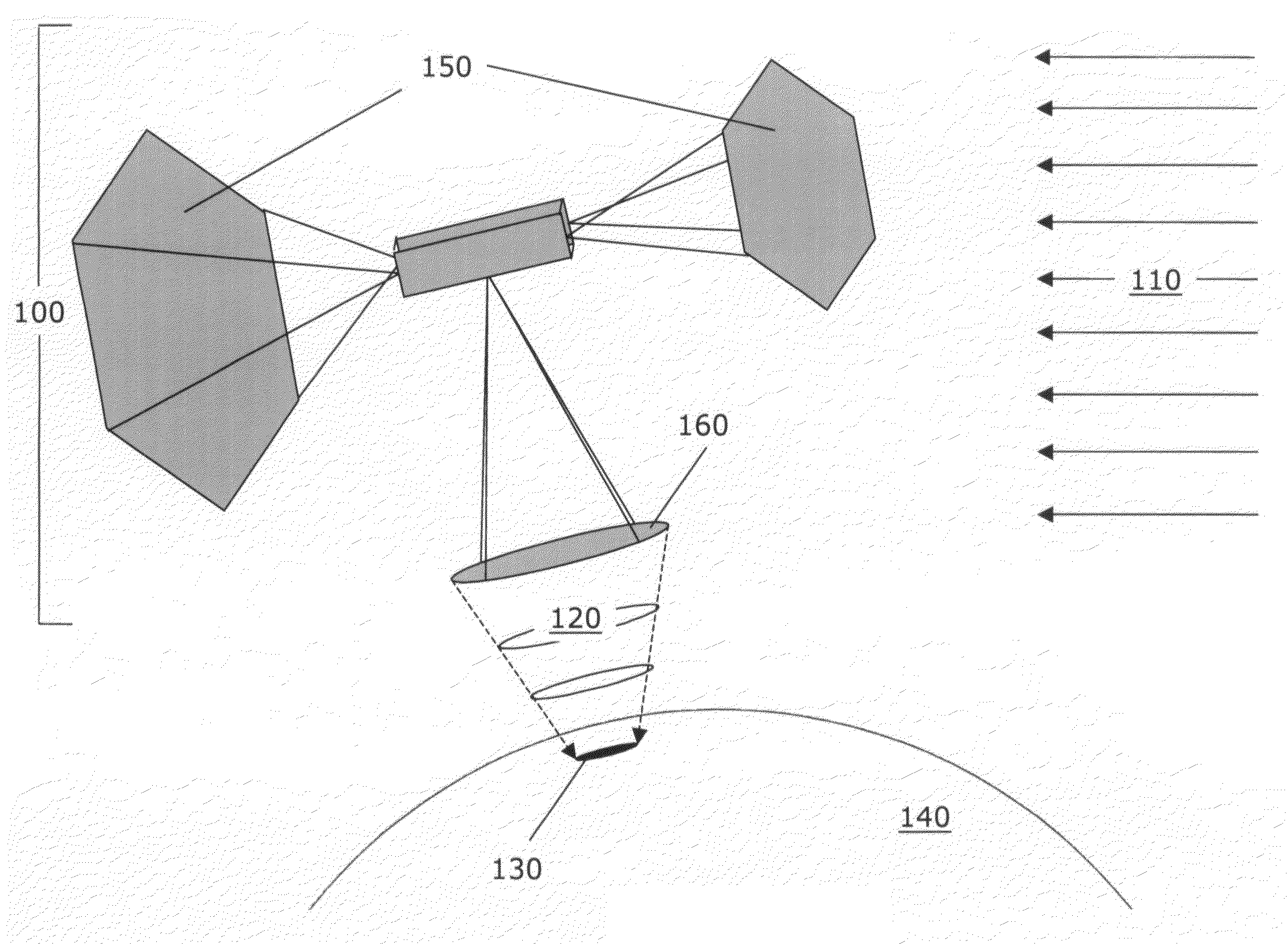
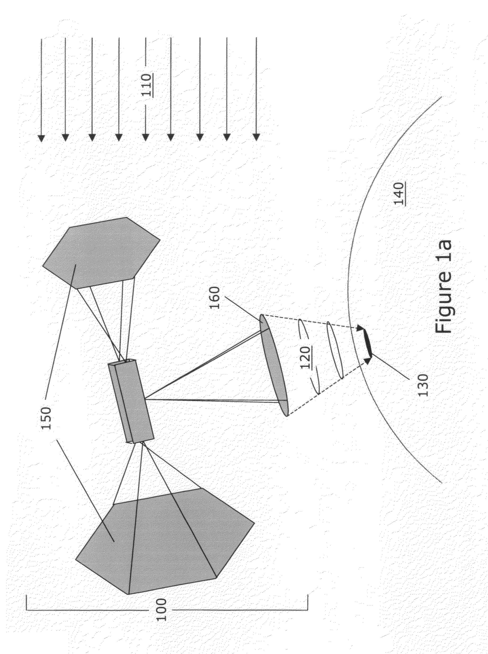
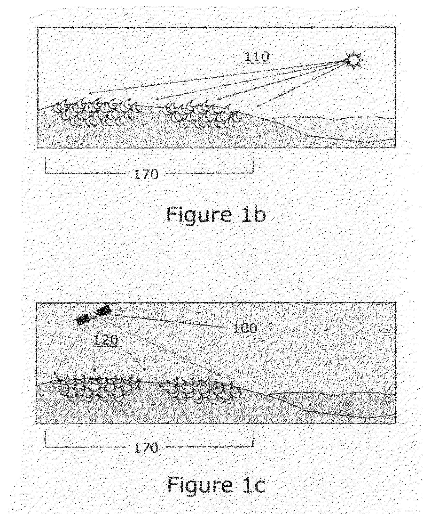
[0095]FIGS. 1b and 1c illustrate the operation of a space solar power satellite for thermochemical processing. When direct sunlight is available, as shown in FIG. 1b, concentrators 170 receive solar energy 110 from the sun and convert it, through thermochemical processes, to chemical energy. When direct sunlight is not available to the concentrators, as shown in FIG. 1c, the concentrators 170 track and point at the powersat 100, receiving and intensifying radiant energy 120 for use in the thermochemical process. Operation in this manner improves the overall productivity of the ground facility since it is able to make use of free energy from the sun.
[0096]One way to facilitate thermochemical processing in conjunction with electricity production, as suggested in FIGS. 2a and 2b, is to place rectennas 220 and thermochemical processors 170 in close proximity on the ground. In this case it is preferable to direct the powerbeam to area of the thermochemical process system only when the sun is not available; otherwise, when the concentrators associated with the thermochemical process are pointed at the sun, they would not be making use of the energy in the powerbeam. This is accomplished by shifting the shape of the powerbeam.
[0097]More generally, in order to achieve maximum end-to-end power transmission efficiency using a powerbeam, a cross-sectional energy density in the shape of a Gaussian distribution is required in what is known as the “main lobe” of the electromagnetic beam, as shown in FIG. 2a. A typical Gaussian distribution is one in which the intensity (watts/m2) at the center of the powerbeam is ten-times greater than the intensity at the edge of the powerbeam. Even when using a Gaussian distribution, however, some of the transmitted energy goes into any one of a larger number of “side lobes” that are spatially distributed around the main lobe. A main lobe in the shape of a Gaussian at the receiver may be formed by transmitting a powerbeam in the shape of the Gaussian from a circular transmitting antenna. However, a variety of other, less optimal powerbeam shapes may also be formed using various methods. For example, one method for forming a powerbeam with a different cross-sectional energy distribution is to use a non-circular transmitter.
[0114]An advantage of the configuration of FIG. 5a is the substantial amount of recuperative heat exchange. This reduces the amount of energy that is required for the net chemical process; it also simplifies fluid control since it allows relatively cool fluids to be transported to and from the thermal receiver and its associated components.
[0116]The configuration of FIG. 5c provides an additional improvement over the configuration of FIG. 5b in that there is no separate high temperature heat exchanger. Integrating the chemical reactor and the high temperature heat exchanger facilitates heat transfer since the endothermic reaction process otherwise tends to cool the fluid and therefore provides greater heat flow from the thermal receiver cavity wall into the reaction channels. It also facilitates greater overall chemical conversion, since equilibrium conversion is directly proportional to temperature for endothermic chemical reactions. This is particularly advantageous since material properties may likely limit the temperature at which thermal receivers can be operated (and therefore would also limit heat transfer rates and chemical conversion). Accordingly, the configuration of FIG. 5c is preferred over the configurations of FIGS. 5a and 5b.
[0120]At least a portion of the thermochemical processing system needs to be located at or in close proximity to the focal point of the concentrator in order to minimize thermal losses. Accordingly, this places volumetric limitations on some of the subsystems and components that make up the thermochemical processing system.
[0128]Microchannel process technology provides several advantages for thermochemical processing systems, including:[0129]Efficient heat transfer, reactions and separations. Due to their small cross-sectional dimensions, microchannel heat exchangers, chemical reactors and separators operate with high heat transport rates despite relatively low temperature differences.[0130]Process intensive operations. Microchannel heat exchangers and reactors typically obtain internal heat fluxes of 10-100 watts/cm2 and heat transfer power densities of 10-50 watts/cm3 or higher. For a system that processes about 100 kWr power from a solar concentrator, this translates to a hardware volume of about 2 to 10 Liters (0.002 to 0.01 m3) for the high temperature microchannel reactor. The overall hardware volume for a complete microchannel process network, comprising those unit operations that would be placed at the focal point of a 100 kWr parabolic dish concentrator unit, is preferably be smaller than about 0.1 to 1.0 m3.[0131]Modular designs support modular construction/installation and maintenance approaches. The compact size and modular nature of microchannel process technology readily adapts itself to the installation of modules at the focal points of concentrators. Reliability can be enhanced through the use of separately addressable modules, which can be turned off or shut down in response to variations in energy input, product demand, or failures within individual units. The relatively small size also facilitates selected forms of maintenance, such as changing out individual units or systems. With conventional hardware, unit sizes, which may be one-to-two orders of magnitude larger than their corresponding microchannel units, may be too large to readily enable changing out of individual reactors, heat exchangers, or entire systems, etc.
[0141]FIG. 10b additionally shows slots 1010 for the placement of electrical resistance heaters, which can aid startup of the system as well as serve as a source of supplemental heat during operation. Note however that electrical resistance heaters can be added to the receiver via any number of ways, such as by wrapping the outside of the outermost cylinder with a flexible electrical resistance heater prior to covering the receiver system with an insulating material. Alternately, to reduce machining costs, electrical resistance heaters can be added to the outside of cylinder 820.
[0142]In operation, solar or other radiant energy is preferably intensified by a concentrator and directed into the thermal receiver cavity, where photons contacting the cylinder walls are ...

Benefits of technology

[0030]An “absorption enhancement” is an element of a thermal receiver and increases the ability of the receiver to absorb radiant energy and convert it to heat. As examples, absorptive coatings, susceptor mat...

Abstract

Processes and methods of producing fuels and other chemicals whereby a substantial portion of the chemical energy of the product is provided by solar energy (110) or a powerbeam (120) consisting of microwave, laser or other radiant energy, and performing thermochemical processes. Systems and applications include using radiant energy to drive moderate- to high-temperature endothermic reactions, followed by downstream chemical reactions and separations to create the desired chemical product.

Application Domain

Technology Topic

Image

  • Process and method of making fuels and other chemicals from radiant energy
  • Process and method of making fuels and other chemicals from radiant energy
  • Process and method of making fuels and other chemicals from radiant energy

Examples

  • Experimental program(3)

Example

EXAMPLE 1
The Invention(s) When Operated for the Production of Propellants and Other Chemicals on the Surface of Mars
[0183]Plans for the exploration of Mars include the production of propellants and other chemicals using feedstock materials from the Martian atmosphere. For example, the document, “Human Exploration of Mars: The Reference Mission of the NASA Mars Exploration Study Team” (NASA Special Publiction 6107), presents a preliminary description of a propellant production plant that produces 5.8 metric tones (MT) of methane (CH4) and 20.2 MT of oxygen (O2), to be used as propellant for the return of humans to Earth. The feedstocks for this are carbon dioxide (CO2) and hydrogen (H2). Methane is described as being produced through the use of the exothermic Sabatier Process Reaction:
CO2+3H2→CH4+H2O,
and oxygen can be produced by two alternative processes, water electrolysis and CO2 electrolysis. More recently, the Reverse Water Gas Shift (RWGS) reaction has been identified as an alternative to the CO2 electrolysis step. The RWGS reaction is endothermic in nature and is as follows:
CO2+H2→CO+H2O
[0184]Since the amount of “equilibrium conversion” of CO2 into CO, in the endothermic RWGS reaction, is directly proportional to temperature—higher temperatures result in more CO—high temperature heat is desirable. This makes the RWGS reaction a good candidate for the concept of using concentrated radiant energy in support of thermochemical processing. On Mars, energy for the reaction would be provided by configuring a RWGS microchannel reactor as part of a thermal receiver such as in FIG. 3. An intermediate, recuperative microchannel heat exchanger would also preferably be used to cool the products of the reaction, giving up their heat to preheat the reactants.
[0185]An alternative approach involves starting the RWGS reaction out at a low temperature while heating the reacting stream to a higher temperature as the reaction proceeds in what is called a “differential temperature microchannel reactor”. This concept, which makes more efficient use of the energy needed for the reaction, has also been demonstrated at PNNL. See U.S. Pat. No. 7,297,324, TeGrotenhuis, W., et.al., “Microchannel reactors with temperature control”, 2007.
[0186]Thermochemical processing is also relevant for capturing and compressing CO2 from the martian atmosphere. For example, absorption and adsorption methods have been examined. In each case, heat is generated during the sorption process and must ultimately be rejected to the martian atmosphere. Also, heat must be added to desorb CO2 from the sorption media. Since the temperatures required for the desorption steps are at most moderate, the efficiency of this system operation is highest if the sorption process is thermally integrated with other thermal process units, such as through the use of heat from a moderate temperature exothermic reaction (e.g., the Sebatier Process Reaction) to provide heat for desorption.
[0187]Finally, thermochemical water-splitting, which will be highlighted in the following example, is another alternative thermochemical process that is relevant for the Mars application. Here, heat is supplied to a network of reactors, heat exchangers and separators for the purpose of producing H2 and O2 from water. It is therefore an alternative to water electrolysis.

Example

EXAMPLE 2
The Invention(s) When Operated for the Production of Propellants and Other Chemicals on the Lunar Surface
[0188]Data from the Lunar Prospector and Clementine missions suggest that water (and perhaps other volatiles) is present in cold traps on the lunar surface, in the vicinity of the north and south poles of the Moon. Upon confirmation, it is anticipated that lunar water will be used as feedstocks for producing oxygen and oxygen-fuel propellant mixes for future human missions to the Moon.
[0189]Based on an assumption of two missions per year, lunar outposts are expected to require about 8-10 MT of oxygen per year. Hydrogen and oxygen can be produced from lunar water through electrolysis, or alternately, through the use of a thermochemical water-splitting process, such as any number of such processes that are currently under investigation for terrestrial applications. These include but are not limited to the following listing: [0190] Zinc oxide process [0191] Cadmium carbonate process [0192] Sodium manganese process [0193] Iron oxide process [0194] Hybrid copper chloride process [0195] Sulfur iodine process [0196] Hybrid sulfur process [0197] Calcium-iron bromide-2 process (also known as the UT-3 cycle)
[0198]See Steinfeld, A., “Solar Thermochemical Production of Hydrogen—A Review”, Solar Energy 78 (2005) 603-615.
[0199]Energy for the thermochemical production of hydrogen and oxygen from water can be provided by directing radiant energy onto or through a concentrator, which reflects and/or focuses the energy onto a thermal receiver where the majority of the photons are absorbed, producing heat. This heat is either used a) to directly heat a unit that performs an endothermic chemical process, b) to directly heat a fluid stream, containing chemicals that are to be subsequently processed in a unit performing an endothermic chemical process, or c) to heat a separate heat transfer fluid, which provides heat to a unit that performs an endothermic chemical process.
[0200]As mentioned previously, uncertainty currently exists regarding the form and composition of volatiles that may be present in the lunar cold traps. If volatiles other than water are present, as may be the case particularly if comet impacts are a source of the volatiles, then other compounds that may be present include hydrocarbons, carbon dioxide, carbon monoxide and ammonia, each of which would be present as ices. Accordingly, there may be many other options for space-resource-based-chemical products on the Moon that could make use of the invention(s) described herein.
[0201]For example, if carbon dioxide is present, it could be reacted with hydrogen (produced from water using electrolysis or a thermochemical water-splitting process) via either the endothermic RWGS reaction or the exothermic Sebatier Process Reaction, each of which was discussed previously. Methane, from the Sebatier Process Reaction, could be used directly as rocket fuel. Alternative potential fuels that could be produced, which are more readily storable than hydrogen or methane, include alcohols (e.g., methanol or ethanol which could be produced in appropriate synthesis reactors) and longer-chain hydrocarbons (which could for example be produced in a Fischer-Tropsch process reactor).
[0202]Finally, for logistics reasons, it may be desirable to locate the chemical processing hardware within a “cold trap” on the lunar surface, such as within a deep crater near either the north or south poles of the Moon. In this case, it may also be appropriate to consider beaming power into the crater either from a location on the surface, such as the crater rim, or from a location in space, such as a powersat in a polar lunar orbit. For the former case, the original energy source may be photovoltaics or another form of solar energy conversion or it may be another source such as a nuclear reactor. With regard to the latter case, although it may seem difficult to contemplate beaming power from an orbiter, it is noted that the cost of placing hardware in lunar orbit is considerably less than placing hardware on the lunar surface. This is moreso true with the Moon than with Mars, where there is an atmosphere for aerobraking.

Example

EXAMPLE 3
The Invention(s) When Operated for the Production of Chemicals on Earth
[0203]Terrestrial applications encounter a different cost dynamic than applications on planetary bodies. As opposed to the lunar case, where it is less expensive to place hardware mass in orbit than on the surface, for applications on Earth it is generally less expensive to retain hardware on the surface than place it in orbit. However, there are still instances where orbiting systems may provide substantial cost advantages.
[0204]For terrestrial applications, the inventions described herein consist of surface installations, where the concentrators, thermal receivers and thermochemical processor systems are located. In one preferred embodiment, the system consists of a segmented-mirror, parabolic dish concentrator that tracks the sun during the daytime, delivering 100 kWr (kilowatts of radiant energy) to the thermal receiver. Portions of the thermochemical processor, located at or in close proximity to the focal point of the concentrator, use the heat to support moderate- to high-temperature, endothermic chemical operations. During the portion of the day when the sun is unavailable, such as during the nighttime, the system may also track a powersat transmitter that redirects/reflects sunlight to the concentrator or that beams radiant energy to the ground facility.
[0205]Most preferably, the powersat transmits microwave energy to the surface installation. In an alternative embodiment, the surface facility tracks and receives energy only from the powersat.
[0206]An example of a system that could be commercially viable in the near-term is one that produces hydrogen from natural gas. Here, the concentrators provide the high temperature heat that is necessary to support an endothermic steam reforming operation within the thermal receiver, converting methane and steam to synthesis gas. The generalized equation for methane steam reforming is:
CH4+H2O→3H2+CO
[0207]Note however that this equation assumes complete conversion of carbon to carbon monoxide; in reality, carbon dioxide will also be formed, so a greater proportion of water is needed than the equation implies in order to approach complete conversion of methane. A thermal receiver, performing the steam reforming reaction within embedded microchannels, should be able to obtain a component thermochemical efficiency of at least 40%, and may be able to reach in excess of 60%.
[0208]Downstream separations, such as using a palladium membrane, can provide purification of the product stream. Other reactors in the system, also downstream of the reforming reactor, could perform the water-gas-shift reaction,
CO+H2O→CO2+H2
which further converts steam and carbon dioxide to additional hydrogen and carbon dioxide. Networks of this sort should obtain reasonable thermochemical efficiencies, in excess of 30%, if the reactors, heat exchangers, and separators are integrated into an efficient thermochemical processing system.
[0209]Other useful chemical products are possible. For example, a modification to the system that processes natural gas would enable the production of ammonia, a chemical that is useful in agricultural markets, or alternative liquid hydrocarbon fuels such as methanol or long-chain hydrocarbons (via the Fischer-Tropsch process reaction).
[0210]It is also possible to use radiant energy thermochemical processing to produce hydrocarbons using water and atmospheric carbon dioxide as feedstocks. For example, hydrogen could be produced using a thermochemical water-splitting process and carbon dioxide can be extracted from the atmosphere using an endothermic sorption process. A high-temperature, reverse-water-gas shift reaction, receiving solar energy as its heat source, would produce carbon monoxide from hydrogen and carbon dioxide. If an excess of hydrogen is used, higher conversions are obtained and the resulting product (synthesis gas) can then be converted to methanol, Fischer-Tropsch long-chain hydrocarbons, or other useful products.
[0211]As discussed above for the Mars and Moon applications, the capacity factor for the ground-based systems can be increased through the utilization of orbiting assets, such as powersats that reflect/redirect solar energy or beam microwaves or laser energy to the ground system. The concept that is contemplated is an alternative to historical proposals for space-solar power, which have typically focused on producing power for the terrestrial electricity market. Usually the orbiting unit converts solar energy to microwave or laser energy, beaming photons to ground-based receivers (rectifying attennas or photovoltaics) which produce electricity.
[0212]Alternately, to support the production of energy fuels and other chemicals, the beam from a powersat can be used to support thermochemical processing. Since the orbiting units can direct energy to radiant energy receivers at any time of day (or night), the capacity factor of the ground facility is increased without a net increase in the capital cost of the ground facility. The marginal cost is the cost of establishing and operating the orbiting systems.
[0213]To maximize value, the ground facility might utilize solar energy from the sun when it is available while also utilizing other radiant energy from one or more powersats. Capacity factors could conceivably be increased from a value of about 20%-25%, if only the sun is tracked, to double or triple that, or even higher, depending upon environmental (e.g., the need to maintain diurnal conditions) or other factors.
[0214]With multiple facilities located around the world, powersats could provide energy throughout the day by directing their output first to one terrestrial system, then to others, or to other applications, as they orbit. Other applications could include providing radiant energy to rectenna systems or providing radiant energy to heat or otherwise support agricultural areas, supplementing solar energy in support of crop growth or providing heat for crops that were in danger of frost. Thus, the capital, operating and maintenance costs associated with the orbiting assets could be amortized amongst multiple applications.
Preliminary Calculation for Human Missions to Mars
[0215]The amount of solar or other radiant energy that is needed for the thermochemical process depends in part on the efficiency with which the process is operated. We can realistically expect that the efficiency of the overall process, including the component efficiencies of the concentrator and thermal receiver units and all thermochemical unit operations, will typically be in the range of about 200%-40%. With this in mind, an example calculation was performed that estimates the amount of required energy based upon an assumption that the thermochemical process system operates with a thermochemical efficiency of about 250%.
[0216]The example calculation also notes that 5.8 metric tones (MT) of methane is desired and that methane has an energy content of about 15.42 kWh per kg (kilowatt-hours of chemical energy per kilogram), based on the higher heating value of methane). Then the total amount of energy required by the system to produce the methane product is:
Thermal Energy Required = 5.8 MT × ( 15.42 kWh / kg ) × ( 10 3 kg / MT ) / 0.25 = 3.58 × 10 5 kWh t
where kWht represents kilowatt-hours of thermal energy. The approximate size of the concentrator can be estimated by assuming that the system operates, due to a diurnal effect, with a capacity factor of 25% for one Earth year (8760 hours). Assuming that direct solar energy is the input, then noting that the solar flux at Mars is about half that at Earth's surface, or about 500 W/m2, we can estimate the size of a solar concentrator to be:
Area = 3.58 × 10 5 kWh × 10 3 w / kW / 0.25 / ( 500 w / m 2 ) / ( 8760 hours ) = 81.7 m 2 Radius = SQRT [ 1.7 m 2 / 3.14159 ] = 5.1 meters
[0217]At this size, it is clear that a parabolic mirror concentrator approach could be applied.
[0218]Assuming that a powersat would have an orbital period of one Mars day, and that the powerbeam would have a power density at Mars' surface that is equal to the solar energy power density at Mars, the thermochemical process system would have to operate at only_the rate required for the system that uses direct solar only. Therefore, the hardaware volume and mass for the thermochemical process system is also reduced by a factor of about 4.
[0219]Note that this calculation was a Rough-Order-of-Magnitude (ROM) calculation. Significant uncertainties include seasonal effects, such as martian duststorms, the efficiency of the thermochemical process system and the flux at the surface of Mars from an orbiting transmitter. However, the calculation still provides insights on the approximate size (again, ROM) for a radiant-energy-powered thermochemical processing plant that produces methane and oxygen on Mars.
Preliminary Calculations for Mars Robotic Sample Return Mission
[0220]Similar calculations can be performed for robotic missions to Mars assuming that we need, say, about 200 kg of methane. For this calculation we will further assume that a radioisotope thermoelectric generator will be brought along and that it can provide heat for low- to moderate-temperature endothermic operations; therefore the concentrator must only provide heat for the high-temperature operations. Thus for this example calculation we are only interested in using solar energy as a source of high temperature heat for the endothermic RWGS reaction.
[0221]Calculations can be performed that show that for every kilogram of CH4 to be produced about 3.2 kilograms (114.3 moles) of CO must ideally also be produced. Thus, the required production of CO is about 640 kg (22,860 moles). The endothermic energy requirement for the RWGS reaction is about 41 kJ/mole (CO), where kJ represents “kilojoules”. Based upon this, an assumption that the overall efficiency of the process is 25%, and using the same calculation method as in the previous example, we calculate the thermal energy requirement to be:
Thermal Energy Required = 22860 moles × 41 kJ / mole / 0.25 = 2749 MJ
where MJ represents megajoules (i.e., 1,000 kJ). This is equivalent to about 1041 kWh.
[0222]Assuming that the mission involves a stay on the martian surface of only 90 days and that the capacity factor for the concentrator/chemical processor is only 25%, we calculate the required concentrator area and radius to be:
Area = 1041 kWh × ( 1000 w / kWh ) / 0.25 / ( 500 w / m 2 ) / 2160 hours = 3.86 m 2 Radius = SQRT [ 3.86 m 2 / 3.14159 ] = 1.11 meters
[0223]This implies that we need a concentrator with a radius of about 3.6 feet.
[0224]This value is already quite small; while an orbiting asset such as a powersat could allow the required concentrator area to decrease, a better advantage might be that the orbiting asset allows the system to produce the required amount of propellant in about_of the time, e.g., about 22-23 days.
Preliminary Calculation for Lunar Propellant Production
[0225]As mentioned previously, lunar outposts are expected to require about 8-10 MT of oxygen per year, based on the assumption of two manned missions to the Moon each year. Assuming that water ice is found in polar regions, we can calculate the energy requirements and the concentrator area and radius by noting that hydrogen has a higher heating value of about 142.1 MJ/kg and that the process that produces O2 from water will also produce about 2 kg of H2 for each 16 kg of O2. For the case where direct solar is used for thermochemical water-splitting, as discussed previously, with an assumption that the overall process is 25% efficient we calculate the thermal energy requirement to be:
Thermal Energy Required = 10 MT O 2 × 1000 kg / MT × ( 2 / 16 kg H 2 / kg O 2 ) × 142.1 MJ / kg H 2 / 0.25 = 7.105 × 10 5 MJ
[0226]For the concentrator area and radius, we note that the solar flux at the Moon is 1360 W/m2, then assuming capacity factor of 25%:
Area = 7.105 × 10 5 MJ × ( 1000 Wh / 3.6 MJ ) / 0.25 / ( 1360 W / m 2 ) / 8760 hours = 66.26 m 2 Radius = SQRT [ 66.26 m 2 / 3.14159 ] = 4.59 meters
[0227]This is a large structure, compared to the previous calculation for Mars; however, it is not necessarily of large mass. On the Moon, the lack of an atmosphere means that there is no wind loading and of course gravity is only ⅙th g. Therefore, thin-film mirrors with inflatable structures may be an option for the concentrating structure, and it is clear that options include a parabolic mirror and/or a central receiver with heliostat mirrors. At_kg per m2 for thin film materials, the approximate mass for the concentrator alone would be about 44 kg, and since it will probably cost about 50,000 US dollars (or more) per kg to deliver a payload to the Moon, the cost of delivering the concentrator is in the neighborhood of 1.65 million US dollars. This is undoubtedly less than the development cost for the unit.
[0228]In addition, we can consider the case where photovoltaics are used to convert solar energy to electricity which is then used to support electrolysis. Assuming that the photovoltaics are between 10% and 20% efficient, and that the electrolysis process is 50% efficient, we estimate an overall efficiency of 5% to 10%. Further assuming that the photovoltaic power system is able to track the sun, with the same capacity factor as the concentrators for the thermochemical process, one can calculate that the total area require for the photovoltaics is about 165 m2 to 330 m2.
[0229]Alternately, we can also calculate the approximate size of the concentrator if the system includes orbiting transmitters, such as a powersat parked at the Li Lagrangian Point directly between the Earth and the Moon, converting solar energy to microwaves or laser power. Assuming the same flux on the lunar surface, but increasing the capacity factor to 100%, we calculate the area and radius to be 16.6 m2 and 2.30 meters, respectively. This is small enough that a parabolic mirror structure may be appropriate.
[0230]As before, one of the primary advantages of making use of one or more powersats would be the ability to reduce the hardware mass for what must be landed on the lunar surface. While the mass of the concentrator is relatively small, the chemical processor is substantially more massive. Operating with a capacity factor of 100% would shrink this mass by about a factor of 4.
[0231]We can estimate the difference in chemical process hardware mass for the lunar surface application by noting the difference in power rate for the two cases: 90.1 kW and 22.5 kW, for the two cases with and without the powersat, respectively. Using the assumption that the thermochemical process system will be a network of conventional chemical process technology, and assuming that the portions of the system that are dominated by thermal effects have a net heat transport power density of about 0.1 w/cm3 and a hardware density of about 5 grams/cm3, then we can calculate the hardware mass for each case to be, respectively, about 4500 kg and about 1125 kg; i.e., the powersat allows a reduction in hardware mass of about 3375 kg. Again, working with an assumption that each kg of mass to be landed on the Moon costs about 50,000 US dollars, the gross savings associated with the reduction in hardware mass is estimated to be about 168.8 million US dollars, which may be of the same order of magnitude as the cost of the powersat. Note again that these numbers are extremely preliminary; considering that we did not consider major portions of the process system, such as regolith excavation and volatiles extraction, it is probably more appropriate to consider the cost reduction to be in the range of 100 million to one billion US dollars.
Preliminary Calculation for Terrestrial Applications
[0232]Extensive calculations have been performed comparing various chemical feedstocks and operating scenarios for terrestrial applications. These calculations, which have been based upon limiting features of the various chemical processes, such as the amount of highly concentrated radiant energy (for endothermic chemical reactions) and the conversion and selectivity of low- to moderate-temperature exothermic reactions, provide estimates of the potential advantages of a facility that produces solar fuels.
[0233]Consider a thermochemical facility with sufficient numbers of concentrators such that, during periods of bright sunlight, cumulative solar energy rates of 1.0 GWs would be used to drive high-temperature, endothermic chemical reactions. A system based on parabolic dish concentrators at 100 kWs each would require 10,000 dishes to yield a cumulative energy of 1.0 GWs; alternately, a system based on central receiver towers with beam-down optics at 50,000 kWs each would require 20 tower systems.
[0234]For these productivity calculations, it is also assumed that the thermochemical efficiency of the concentrator-receiver-endothermic reactor combination is 40% (except for thermochemical water-splitting where we selected a range of 30-50%). In addition, it is assumed that the thermal energy for low- to moderate-temperature operations such as water vaporization, thermal-swing separations, and distillation, are provided in part through thermal integration with exothermic unit operations and in part through the use of less expensive, parabolic trough concentrators.
[0235]For the calculations, three classes of chemical feedstocks were assumed: Methane (based on natural gas as the feedstock source); methane plus carbon dioxide (based upon the typical products of the anaerobic digestion of biomass); and water and water plus carbon dioxide (as zero-energy chemicals); however, other chemical feedstocks could also be used. Various appropriate assumptions were also made about the yields of downstream reactors and separators, with the specific calculations assuming that the solar fuels to be produced were hydrogen and/or a long-chain hydrocarbon (i.e., through the Fischer-Tropsch reaction).
[0236]Results of the calculations are presented in FIG. 19. In Column (A) of FIG. 19, we consider the thermochemical facility when operated when the sun is available, achieving in this case an average capacity factor of 25%. This is equivalent to full production for six hours per day, 365 days per year. If natural gas is used as a feedstock, the output of the facility is estimated to be 390,000 to 430,000 gallons of gasoline equivalent per day (gge/day). Based on current gasoline usage in the US, this production rate would serve the transportation needs of about 280,000 to 310,000 people. Alternately, if biomass materials or zero-energy feedstocks, such as water and/or carbon dioxide are used, the productivity of the facility is reduced due to the reduced chemical energy content of the reactants.
[0237]Columns (B) and (C) consider operational scenarios where the thermochemical facility is operated with a higher capacity factor than can be afforded with direct solar energy only. In Column (B), it is assumed that natural gas is combusted to bring increase the capacity factor by 65%, bringing the overall capacity factor of the facility to 90%; and in Column (C) it is assumed that a powerbeam from an orbiting facility brings the overall capacity factor to 90%. The latter could be achieved by using solar energy plus the powerbeam or by just using the powerbeam. Of course, other combinations of energy sources and operational scenarios are also possible as ways to increase the overall capacity factor of the thermochemical facility.
[0238]When the facility is operated with an overall capacity factor of 90%, the productivity of the facility increases proportionally. For example, in the case where natural gas is used as the chemical feedstock, the facility's daily production when operated at a capacity factor of 90% is estimated to be about 1,400,000 to 1,600,000 gge/day, enough to serve the transportation needs for a US population of about 1.0 to 1.1 million.
[0239]Calculations also show a potential for the reduction in greenhouse gas emissions. For example, we note that the combustion of one gallon of gasoline, on the average, results in the release of 8.82 kg of carbon dioxide. For the same net chemical energy production (based on the higher heating values of gasoline and methane), the combustion of natural gas would generate only about 6.67 kg of carbon dioxide; accordingly, displacing gasoline with solar fuels derived from natural gas should generally reduce carbon dioxide emissions. However, the actual releases will depend upon the source of the thermal energy that is used in the thermochemical facility.
[0240]Accordingly, FIG. 19 includes estimates of the greenhouse gas emissions (increases and reductions) associated with the operation of the reference thermochemical facility. For cases where only solar energy is used to support the endothermic chemical reactions, for example, Column (A), net carbon dioxide emissions are reduced (compared to using gasoline as a transportation fuel). However, when natural gas is burned to support the endothermic chemical reactions, as in Column (B), mixed results occur. If natural gas is also used as the feedstock chemical for the reaction, net carbon dioxide emissions are increased.
[0241]The best case for greenhouse gas emission reductions occurs when biomass feedstocks are combined with a carbon-neutral energy source, such as beamed, radiant energy from a powersat. In this case, the biomass feedstock brings carbon-neutral, chemical energy content and the powersat supports increased capacity factor for the thermochemical facility. The productivity of the facility as well as its emissions will depend of course upon the capacity factor of the facility and therefore is also dependent upon the power density of the radiant energy beam; for calculations where the capacity factor is assumed to be 90%, approximately 1,000,000 gge/day is produced (equivalent to about 0.24% of the USA's annual oil imports) and carbon dioxide emissions are reduced by 3,300,000 metric tonnes per year. Forty such facilities, each occupying a few square kilometers could reduce USA oil imports by nearly 10%.
CLOSURE
[0242]While preferred embodiments of the present invention have been shown and described, it will be apparent to those skilled in the art that many changes and modifications may be made without departing from the invention in its broader aspects. The appended claims are therefore intended to cover all such changes and modifications as fall within the true spirit and scope of the invention.

PUM

no PUM

Description & Claims & Application Information

We can also present the details of the Description, Claims and Application information to help users get a comprehensive understanding of the technical details of the patent, such as background art, summary of invention, brief description of drawings, description of embodiments, and other original content. On the other hand, users can also determine the specific scope of protection of the technology through the list of claims; as well as understand the changes in the life cycle of the technology with the presentation of the patent timeline. Login to view more.

Similar technology patents

Classification and recommendation of technical efficacy words

  • Increase absorption
  • Increase ability

Organic photosensitive devices

ActiveUS20060032529A1Increase absorptionEfficient deviceSolid-state devicesSemiconductor/solid-state device manufacturingSurface plasmon polaritonNanometre
Owner:THE TRUSTEES FOR PRINCETON UNIV

Uniform delivery of topiramate over prolonged period of time with enhanced dispersion formulation

InactiveUS20050058707A1Enhance bioavailabilityIncrease absorptionNervous disorderCapsule deliveryTopiramateControlled Release Dosage Form
Owner:ALZA CORP

Minimally invasive surgical spinal exposure system

ActiveUS20050277812A1Increase areaIncrease abilityDiagnosticsSurgical field illuminationSpinal operationInterior space
Owner:ZIMMER BIOMET SPINE INC

Illuminative treatment of holographic media

InactiveUS20060281021A1Increase abilityReduce coherenceHolographic light sources/light beam propertiesPhotomechanical apparatusHolographic storageOptics
Owner:AKONIA HOLOGRAPHICS
Why Eureka
Try Eureka