Multi-function vacuum bag for composite part manufacture

a vacuum bag and composite part technology, applied in the field of fabrication or manufacture of composite parts, can solve the problems of large amounts of hazardous air pollutants, large size and geometry of parts produced with closed molds, and high cost of matching metal dies

Inactive Publication Date: 2008-07-31
AMERICAN CONSULTING TECH
View PDF44 Cites 45 Cited by
  • Summary
  • Abstract
  • Description
  • Claims
  • Application Information

AI Technical Summary

Benefits of technology

[0017]In light of the problems and deficiencies inherent in the prior art, the present invention seeks to overcome these by providing a multi-function vacuum bag that provides all-in-one capabilities, namely to function as the vacuum bag, a caul or caul sheet, release layer, a breather, and various other materials. In other words, the present invention vacuum bag is comprised of a suitable composition having properties that allow the vacuum bag to inherently provide all of the necessary functions needed during a vacuum bagging process, without requiring these separate and independent components.

Problems solved by technology

Unfortunately, because of the high cost of matched metal dies and high tonnage presses, parts produced with closed molds are generally limited in size and geometry.
A significant drawback to these “wet” open mold methods of fabrication is the release of large amounts of hazardous air pollutants (hereinafter “HAPs”) into the surrounding atmosphere, which is a matter of great concern both to the Environmental Protection Agency (EPA) and the Occupational Safety and Health Agency (OSHA).
However, it also creates a host of new manufacturing difficulties which, in turn must be overcome.
One ongoing concern is the potential formation of air pockets or voids in the composite part that can result in both structural deficiencies and reduced aesthetics.
Although slowing down the evacuation process can reduce the occurrence of air pockets and wrinkles, it also results in reduced production rates, and therefore increased costs.
Any taped seam in the bag also creates the potential for a pinhole leak, which will cause air to be introduced into the resin stream.
This problem causes a quality issue commonly called “bubble trails.” Such defects that are not corrected during the molding process require costly reworking.
Moreover, if the bag is of inadequate thickness, the induced negative pressure may draw portions of the bag film down into the intricacies in the fiber preform to partially block the flow of the resin.
This phenomenon may require additional flow time to allow the affected area to be filled from another direction, and may also result in a structural defect caused by incomplete wetting of the fiber preform by the resin.
The method of properly installing traditional bags is labor-intensive, especially for very large structures, such as boat hulls.
Furthermore, additional up-front effort must also be spent assembling resin supply and vacuum suction manifolds which connect to the injection and vacuum ports.
It is recognized that it is costly to discard the completed vacuum bag after each use, but as the bag film must be thin and flexible in order to be applied in the first place, it lacks the structural integrity to withstand removal, cleaning and repositioning without tearing.
Therefore, the expensive process of manually assembling the vacuum bag by laying down the bag film, attaching the injection and vacuum ports, and sealing the periphery of the bag against the tooling member must be repeated for each new composite structure which is to be built using the resin infusion process.
A similar problem exists with the bags used in traditional vacuum bagging processes, which have long been used to fabricate laminated composite articles comprised of composite materials that are adhesively bonded together.
When the vacuum induces an internal collapse of the bag against the prepreg fiber reinforcement, the bag has a tendency to restrict the air from freely flowing through the fiber reinforcement, trapping pockets of air and other vapors between the bag and the composite structure.
Unfortunately, conventional vacuum bags that comprise a plastic sheet and that require a sealing tape for sealing against the mold are not robust and durable, and cannot be used to apply more than a few layers of laminates before they must be discarded and replaced.
Fabricating a vacuum bag for each article in a production run is time consuming and expensive.
Moreover, for parts with many layers a large quantity of used vacuum bags will be discarded, adding undesirable solid waste.
Moreover, the bag cannot be manufactured quickly as each layer of silicone rubber takes time to set before the next layer is applied.
Finally, because of its high density and weight a silicone rubber bag does not work well with large open mold tooling members like those used to fabricate boat hulls.
Such a large bag would be too unwieldy and likely to tear under its own weight if handled improperly.

Method used


Image

  • Multi-function vacuum bag for composite part manufacture
  • Multi-function vacuum bag for composite part manufacture
  • Multi-function vacuum bag for composite part manufacture

Examples


example one

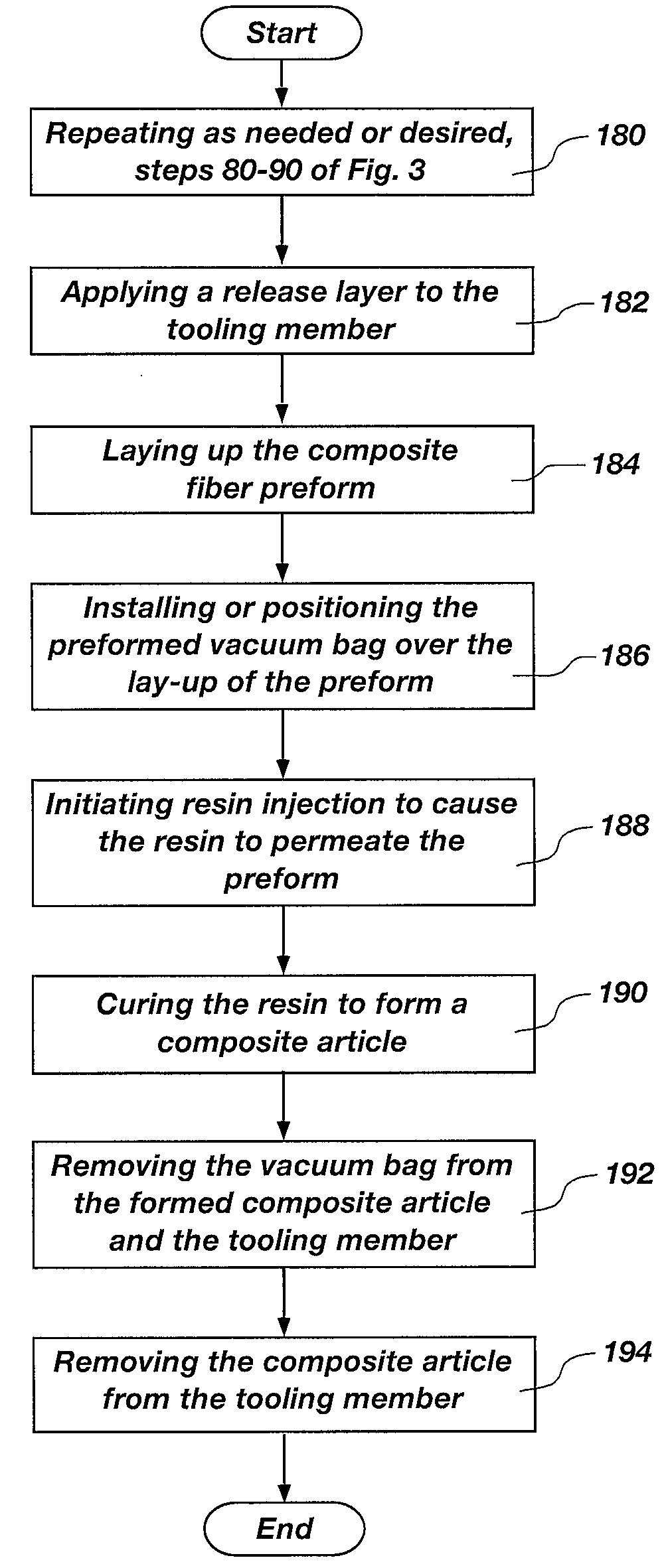
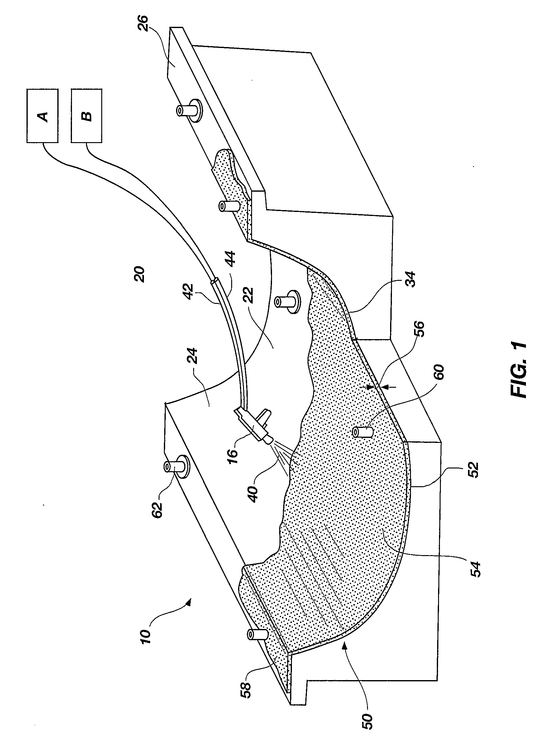
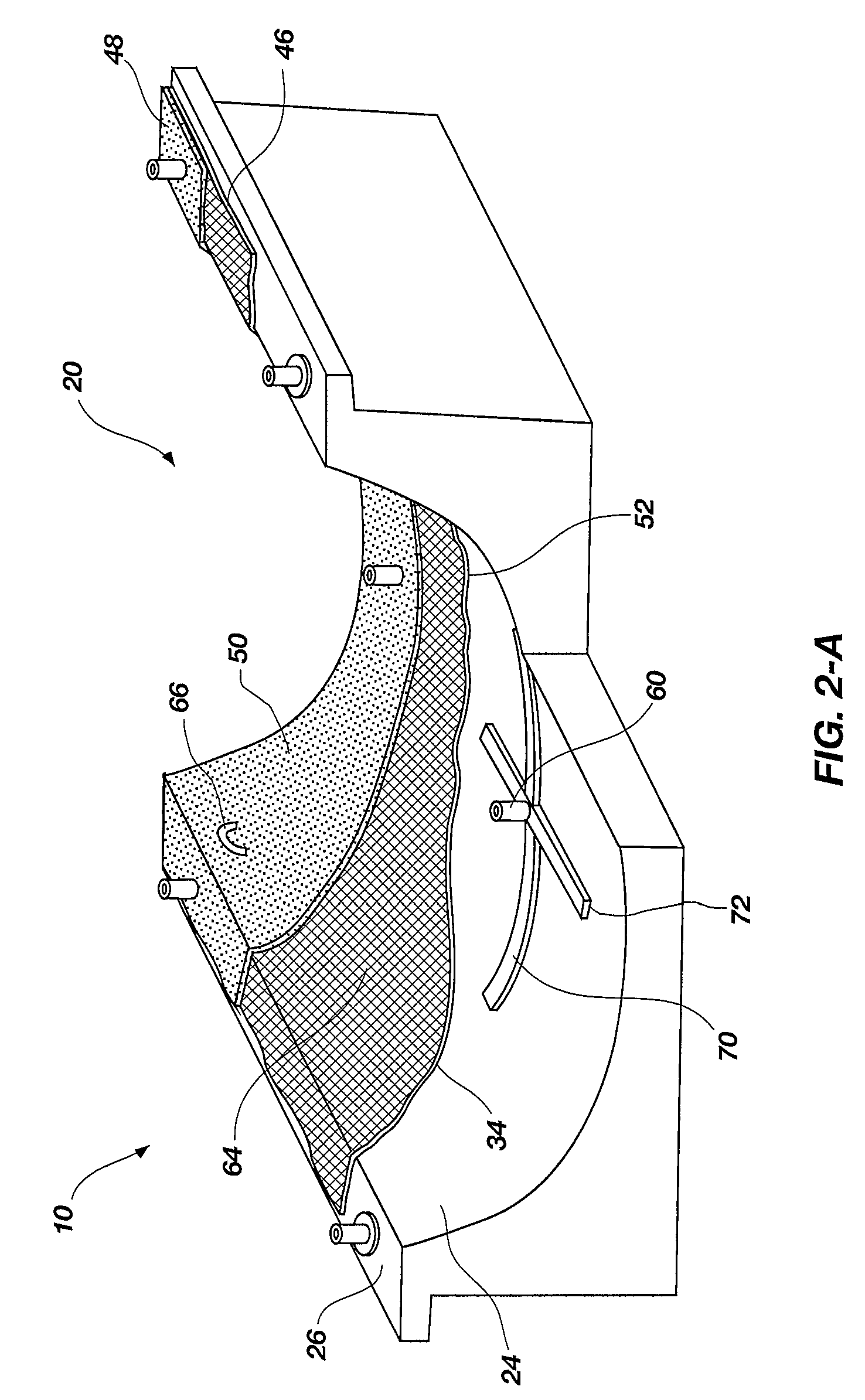
[0123]This prospective example is representative of a bagging system comprising a sprayable, multi-function vacuum bag designed for multi-functional use in composite parts manufacturing. Stated differently, the compositions provided herein allow the multi-function vacuum bag to function as a release, a caul, a breather layer, a vacuum bag, a pliable mold top, etc., each of which can be achieved with the single present invention vacuum bag. As discussed, providing multiple functions allows multiple conventional manufacturing processes to be avoided or eliminated, while producing high quality composite parts. In addition, depending upon the application, the vacuum bag can have multiple life cycles.

[0124]In this example, the multi-function vacuum bag comprises a prepolymer composition made up of a two part polyurea, such as those provided by BaySystems North America, and utilizes a Gusmer spray machine or equivalent for spraying. Specifically, the prepolymer composition contains the fo...

example two

[0138]This prospective example is also representative of a bagging system comprising a sprayable, multi-function vacuum bag designed for multi-functional use in composite parts manufacturing. Stated differently, the compositions provided herein allow the multi-function vacuum bag to function as a release, a caul, a breather layer, a vacuum bag, a pliable mold top, etc., each of which can be achieved with the single present invention vacuum bag. Applications include, but are not limited to autoclave cures, resin infusion cures, prepreg de-bulking and other processes.

[0139]In this example, the multi-function vacuum bag comprises a prepolymer composition made up of a two part polyurea, and utilizes a Gusmer spray machine or equivalent for spraying. Specifically, the prepolymer composition contains the following substances and their respective proportions: an “A” side Polymeric MDI present in an amount by weight about 33% (Ingredients: Diphenylmethane—diisocyanate (MDI), and modified MD...


PUM

PropertyMeasurementUnit
temperaturesaaaaaaaaaa

Abstract

A multi-function vacuum bag for use in the manufacture of composites, wherein the vacuum bag may be configured to provide all-in-one capabilities, namely to function as the vacuum bag, a caul or caul sheet, release layer and/or a breather, as well as to provide other functions. Specifically, the multi-function vacuum bag allows a separate breather or breather material, a separate caul or caul layer, and a release or release layer all to be eliminated, if desired, as the multi-function vacuum bag is capable of performing the functions of each of these once formed. Furthermore, the multi-function vacuum bag may be used with various composite manufacturing process, such as VARTM or resin infusion processes, various vacuum bagging processes, filament winding processes, and others.

Description

RELATED APPLICATIONS[0001]This application claims the benefit of U.S. Provisional Application No. 60 / 879,725, filed Jan. 9, 2007, and entitled, “Multi-Function Vacuum Bag for Composite Part Manufacture,” which is incorporated in its entirety herein.FIELD OF THE INVENTION[0002]The present invention relates generally to the fabrication or manufacture of composite articles, and more particularly to the several components and / or materials used to manufacture composite articles.BACKGROUND OF THE INVENTION AND RELATED ART[0003]Fiber reinforced resin composite articles are fabricated using one of two basic techniques. In a “dry” lay-up process, fiber forms that have been pre-wetted with resin, forming a “pre-preg” structure, are laid up against a mold to provide the proper shape. The process is “dry” because no new resin is introduced to the fiber forms after the material has been laid up against the mold. In a “wet” lay-up process, a dry fiber reinforcement material, otherwise known as a ...

Claims


Application Information

Patent Timeline
Patent Type & Authority Applications(United States)
IPC IPC(8): B32B27/00B29C41/42B29C65/70
CPCB29C70/30B29C70/44Y10T428/1334B29C70/74B29C70/54B29C70/549
Inventor RIDGES, MICHAEL D.MCCARVILL, WILLIAM T.
Owner AMERICAN CONSULTING TECH
Why Eureka
Try Eureka