Master Substrate and Method of Manufacturing a High-Density Relief Structure

a technology of high density relief and master substrate, which is applied in the direction of photomechanical treatment originals, instruments, photomechanical apparatus, etc., can solve the problems of low reflection level, local broadening, and conventional photoresist mastering is the cumulative photon effect, so as to avoid lens contamination and high numerical aperture

Inactive Publication Date: 2008-08-07
MOSER BAER INDIA
View PDF10 Cites 5 Cited by
  • Summary
  • Abstract
  • Description
  • Claims
  • Application Information

AI Technical Summary

Benefits of technology

[0023]The proposed mastering substrate is particularly suitable for near-field mastering. Near field recording is based on an objective lens with a very high numerical aperture. This lens is preferably realized as a solid immersion lens (SIL), which is placed in close proximity of the data layer, distances between 20 and 100 nm are anticipated. Currently, systems with an NA of 1.6 and even 2.0 in combination with 405 nm wavelength laser light are considered as a possible system for next generation optical storage. If such a system is used in combination with conventional mastering substrates based on photoresist, contamination of the lens is likely to occur due to evaporation of all kind of photoresist constituents. However, the master substrates based on inorganic phase-change materials are very advantageous to use because of the avoidance of lens contamination. In such a near-field recording system, a pre-grooved master substrate can be used to master a high-density data pattern. From this relief pattern a stamper can be made that is used for the mass-replication of optical discs, both ROM discs (discs with pre-pits) and recordable and rewritable discs (discs with a pre-groove).

Problems solved by technology

It is well known that ROM discs are read out via phase-modulation, i.e. the constructive and destructive interference of light rays.
During readout of longer pits, destructive interference between light rays reflected from the pit bottom and reflected form the adjacent land plateau occurs, which leads to a lower reflection level.
An additional disadvantage of conventional photoresist mastering is the cumulative photon effect.
This multiple exposure leads to local broadening of the pits and therefore to an increased pit noise (jitter).
Another disadvantage of photoresist materials as used in conventional mastering is the length of the polymer chains present in the photoresist.
Dissolution of the exposed areas leads to rather rough side edges due to the long polymer chains.
In particular in case of pits (for ROM) and grooves (for pre-grooved substrates for write-once (R) and rewritable (RE) applications) this edge roughness may lead to deterioration of the readout signals of the pre-recorded ROM pits and recorded R / RE data.

Method used


Image

  • Master Substrate and Method of Manufacturing a High-Density Relief Structure
  • Master Substrate and Method of Manufacturing a High-Density Relief Structure
  • Master Substrate and Method of Manufacturing a High-Density Relief Structure

Examples


Embodiment Construction

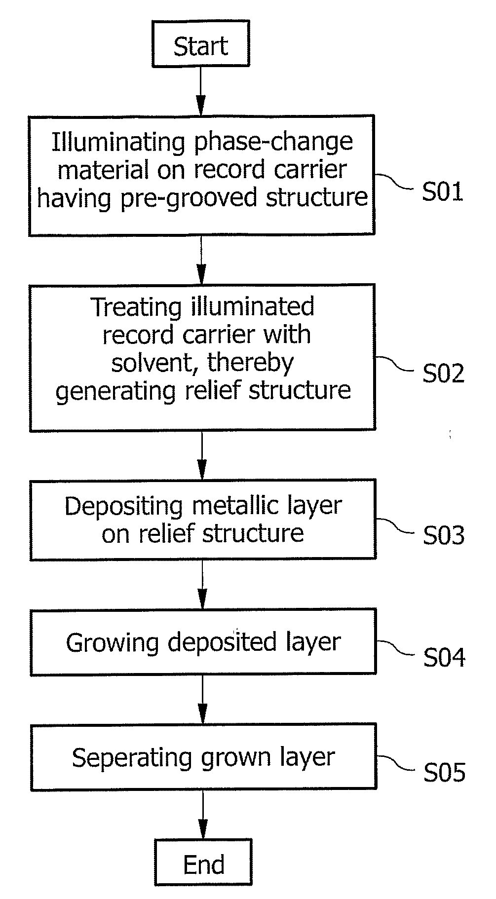
[0033]FIG. 1 shows a schematic set-up of a conventional optical disc drive that can be employed with the present invention. A radiation source 110, for example a semi-conductor laser, emits a diverging radiation beam 112. The beam 112 is made essentially parallel by a collimator lens 114, from which it is projected to a beam splitter 116. At least a part of the beam 118 is further projected to an objective lens 120, which focuses a converging beam 122 onto a master substrate 10. The master substrate 10 will be described in detail with reference to the figures below. The focused beam 122 is able to induce a phase change in the recording layer of the master substrate. On the other hand, the converging beam 122 is reflected into a diverging beam 124 and is then projected further as an essentially parallel beam 126 by the objective lens 120. At least part of the reflected beam 126 is projected to a condenser lens 128 by the beam splitter 116. This condenser lens 128 focuses a converging...


PUM

PropertyMeasurementUnit
wavelengthaaaaaaaaaa
thicknessaaaaaaaaaa
thicknessaaaaaaaaaa

Abstract

The present invention relates to a master substrate (10) for optical recording comprising a recording layer (12) and a substrate layer (14), the recording layer comprises a growth dominated phase-change material, the chemical properties with respect to chemical agents of which may be altered due to a phase change induced by projecting light on the recording layer. For tracking purposes, the substrate layer comprises pre-grooves (16). The present invention further relates to a method of manufacturing a stamper for replicating a high-density relief structure.

Description

FIELD OF THE INVENTION[0001]The present invention relates to a master substrate and to a method of manufacturing a high-density relief structure. Particularly, the present invention relates to providing a high-density relief structure using a conventional optical drive.BACKGROUND OF THE INVENTION[0002]Relief structures that are manufactured on the basis of optical processes can, for example, be used as a stamper for the mass-replication of read-only memory (ROM) and pre-grooved write-once (R) and rewritable (RE) discs. The manufacturing of such a stamper, as used in a replication process, is known as mastering.[0003]In conventional mastering, a thin photosensitive layer, spincoated on a glass substrate, is illuminated with a modulated focused laser beam. The modulation of the laser beam causes that some parts of the disc are being exposed by UV light while the intermediate areas in between the pits remain unexposed. While the disc rotates, and the focused laser beam is gradually pul...

Claims


Application Information

Patent Timeline
Patent Type & Authority Applications(United States)
IPC IPC(8): G03F7/004G03F1/14
CPCG11B7/261G11B7/0901G11B7/26
Inventor MEINDERS, ERWIN RINALDO
Owner MOSER BAER INDIA
Why Eureka
Try Eureka