Laser dicing sheet and process for producing chip body

a technology of laser dicing and chip body, which is applied in the direction of film/foil adhesives, synthetic resin layered products, manufacturing tools, etc., can solve the problems of reducing the light transmission through the dicing sheet, affecting the uniformity of the film thickness, so as to achieve the effect of reducing the amount of light transmitted through the base material and reaching the chuck tabl

Active Publication Date: 2008-08-14
LINTEC CORP
View PDF12 Cites 8 Cited by
  • Summary
  • Abstract
  • Description
  • Claims
  • Application Information

AI Technical Summary

Benefits of technology

[0031]In the present invention, because using polyurethane acrylate film as the most upper layer of a base material, a received damages is small and not be cut fully, even though laser beam is irradiated to the base material. Also, the base material is not damaged and an amount of light transmitted through the base material and reached to the chuck table is decreased. As a result, in the laser dicing, cutting of a laser dicing sheet, damage of the chuck table and fusion of the dicing sheet to the chuck table are prevented which cause manufacturing processes for the chip body by laser dicing can be operated smoothly. Also, by using a polyurethane acrylate film having predetermined proportion of ethyleneoxy group as a base material in the present invention, shape-restoring ability after expanding the sheet is improved and recovering the ring frame can be operated smoothly.
[0032]Hereinafter, the present invention will be explained specifically. A dicing sheet of the present invention is composed of a base material, and an adhesive layer formed thereon.
[0033]As the base material, a resin film whose main constituent is polyurethane acrylate is used. As the polyurethane acrylate film, it is preferable a cured product obtained by irradiating energy beam to a mixture including an energy beam curable urethane acrylate oligomer and an energy beam curable monomer after film forming.
[0034]An energy beam curable urethane acrylate oligomer is obtained by e.g., reacting (meth)acrylate having hydroxyl group with terminal isocyanate urethane prepolymer obtained by reacting polyol compound such as a polyester type or polyether type with polyvalent isocyanate compound. Also, an energy beam curable urethane acrylate oligomer can be obtained by reacting polyol compound with (meth)acrylate having isocyanate group.
[0035]Although the polyol compounds may be any of alkylene diol, polyether type polyol, polyester type polyol or polycarbonate type polyol, more preferable effects is obtained by using polyether type polyol. Also, if it is the polyol, it is not particularly limited and it may be difunctional diol, trifunctional triol, however, in view of availability, general versatility, reactivity and the like, using diol is particularly preferable. Therefore, polyether type diol is preferably used.
[0050]As a film forming method, a flow casting method (casting film forming) is preferably adapted. Specifically, film forming is conducted that after casting liquid composition (before curing resin, solution of resin and the like) on for example, process sheet with thin film shape, then, energy irradiating such as ultra-violet ray, electron beam and the like to the liquid composition by polymerization curing for film forming, thereby, the base material can be manufactured. According to the method, stress to the resin at time of film forming is small and a forming fish eye is small. Further, uniformity of film thickness is high and thickness accuracy is within a range of 2% in normally.

Problems solved by technology

There is a problem that, at this time, the laser beam transmits through the dicing sheet and a chuck table is damaged.
Further, there is a problem that a surface of the dicing sheet, which contacts with the chuck table heated by the laser beam, is melting and is fused with the chuck table.
However, after the laser dicing, it is necessary to peel one of the structure layers of the base material which causes complicated process.
Also, the expanding is sometimes impossible because the expanding film is cut by the laser beam sometime.
However, in this Patent Document 3, it is intended to apply the blade dicing and specific problems of the laser dicing as mentioned above are not recognized.
It is expected that film damage is relatively minor even though the laser beams is directly irradiated, because a crosslink density of a film obtained from film forming and curing the urethane acrylate oligomer is high.
However, although the film described in Patent Document 3 excelled in expanding ability, the expanded film has such character that it is hard to return its original shape as being elongated.
In this status, the sagging dicing sheet cannot be stowed to the recovery cassette smoothly, because the dicing sheet contacts other recovered ring frame and sheet.
According to the above results, a dicing sheet using a film described in Patent Document 3 has not been realized still, inevitably, there is no utilization as a laser dicing sheet.

Method used


Image

  • Laser dicing sheet and process for producing chip body
  • Laser dicing sheet and process for producing chip body
  • Laser dicing sheet and process for producing chip body

Examples


example 1

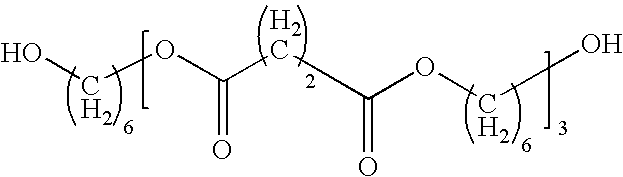
[0091]2-hydroxyethyl acrylate (2HEA), 4,4′-dicyclohexyl methane diisocyanate (H12MDI) and polyester polyol shown by a following formula (Polyol: molecular weight 826) are prepared at molar ratio 2HEA:H12MDI:Polyol=2:4:3. Initially, H12MDI and polyester polyol are reacted, 2HEA is added to the obtained product so as to obtain urethane acrylate oligomer.

[Chemical Formula]

[0092]

[0093]Then, 50 parts by weight of the urethane acrylate oligomer, 50 parts by weight of an energy beam curable monomer (isobornyl acrylate) and 3 parts by weight of a photoinitiator (IRGACURE184 produced by Ciba Specialty Chemicals) were blended and a film forming coating liquid was obtained.

[0094]Resin composition layer was formed by coating the above coating liquid to a silicone release treated polyethylene terephthalate (PET) film (release film; SP-PET3801 produced by Lintec Corporation) by fountain die method as being its thickness is 100 μm. Immediately after coating, laminating a same silicone release trea...

example 2

[0099]2-hydroxyethyl acrylate (2HEA), isophorone diisocyanate (IPDI) and polytetramethyelene glycol (PTMG: weight-average molecular weight 2,000) are prepared at molar ratio 2HEA:IPDI:PTMG=2:5:4. Initially, IPDI and PTMG are reacted, 2HEA is added to the obtained product so as to obtain urethane acrylate oligomer.

[0100]Then, 50 parts by weight of the urethane acrylate oligomer, 50 parts by weight of an energy beam curable monomer (isobornyl acrylate) and 0.5 parts by weight of a photoinitiator (DALOCURE1173 produced by Ciba Specialty Chemicals) were blended and a film forming coating liquid was obtained.

[0101]Subsequently, a base material film was produced by using the obtained coating liquid, according to the same manner as in the example 1. And providing an adhesive layer according to the same manner, a laser dicing sheet was obtained. Results are shown in Table 1.

example 3

[0102]2-hydroxyethyl acrylate (2HEA), isophorone diisocyanate (IPDI) and polypropylene glycol (PPG: weight-average molecular weight 2,000) are prepared at molar ratio 2HEA:IPDI:PPG=2:5:4. Initially, IPDI and PPG are reacted, 2HEA is added to the obtained product so as to obtain urethane acrylate oligomer.

[0103]Then, 50 parts by weight of the urethane acrylate oligomer, 50 parts by weight of an energy beam curable monomer (isobornyl acrylate) and 0.5 parts by weight of a photoinitiator (DALOCURE1173 produced by Ciba Specialty Chemicals) were blended and a film forming coating liquid was obtained.

[0104]Subsequently, a base material film was produced by using the obtained coating liquid, according to the same manner as in the example 1. And providing an adhesive layer according to the same manner, a laser dicing sheet was obtained. Results are shown in Table 1.


PUM

PropertyMeasurementUnit
thicknessaaaaaaaaaa
thicknessaaaaaaaaaa
thicknessaaaaaaaaaa

Abstract

An object of the present invention is to provide a laser dicing sheet which is capable of preventing cutting of dicing sheet by laser beam, damage of the chuck table and fusion of the dicing sheet to the chuck table.
A laser dicing sheet according to the present invention comprising a base material comprising a polyurethane acrylate; and an adhesive layer formed on one surface thereof.

Description

FIELD OF THE INVENTION[0001]The present invention relates to a laser dicing sheet suitably used for fixing a work so as to make into chips by dicing with laser beam and a manufacturing method for chip body with suitably using the laser dicing sheet.DESCRIPTION OF THE RELATED ART[0002]In recent years, since there is a case that a work is difficult to cut by a blade dicing, a laser dicing is particularly attracted which is capable of cutting the work by the laser dicing. An example of a laser dicing sheet used for the laser dicing is disclosed by the applicant (Patent Document 1).[0003]In the laser dicing, a work fixed on a dicing sheet is cut by scanning the laser beam. In this case, a focal point of the laser beam moves as following, namely, the focal point is accelerated from a surface of the dicing sheet wherein the work is not attached (an outer edge portion of the work), scanning on a surface of the work at constant speed, the focal point is decelerated at the opposite outer edg...

Claims


Application Information

Patent Timeline
Patent Type & Authority Applications(United States)
IPC IPC(8): B23K26/00B32B27/40
CPCC09J7/0282C09J2203/326C09J2205/31H01L2221/68327H01L21/6836H01L21/78C09J2475/006C09J7/25Y10T428/31551C09J2301/416
Inventor WAKAYAMA, YOJISATO, YOSUKETAYA, NAOKI
Owner LINTEC CORP
Why Eureka
Try Eureka