Ebullated bed hydroprocessing systems

a technology of ebullated bed and hydroprocessing system, which is applied in the direction of aromatic hydrocarbon hydrogenation, hydrocarbon oil cracking, chemical/physical/physicochemical processes, etc., can solve the problems of premature deactivation of catalyst, large molecules that are too large to diffuse into the pores of the ebullated bed catalyst, and it is difficult to upgrade heavy oil feedstock rich in asphaltenes using conventional ebullated bed hydroprocessing systems. achieve the effect of improving the quality

Active Publication Date: 2008-08-14
HEADWATERS TECH INNOVATION LLC
View PDF99 Cites 55 Cited by
  • Summary
  • Abstract
  • Description
  • Claims
  • Application Information

AI Technical Summary

Benefits of technology

[0017]The present invention relates to ebullated bed hydroprocessing methods and system for improving the quality of a heavy oil feedstock that employ both a porous supported catalyst and a colloidal or molecular catalyst. The invention also includes methods for upgrading an existing ebullated bed hydroprocessing system by augmenting or replacing at least a portion of the porous supported catalyst with a colloidal or molecular catalyst. The colloidal or molecular catalyst overcomes at least some of the problems associated with the use of porous supported catalysts in upgrading heavy oil feedstocks. These include more effective processing of asphaltene molecules, a reduction in the formation of coke precursors and sediment, reduced equipment fouling, increased conversion level, enabling the reactor to process a wider range of lower quality feedstocks, elimination of catalyst-free zones in the ebullated bed reactor and downstream processing equipment, longer operation in between maintenance shut downs, and more efficient use of the supported catalyst if used in combination with the colloidal or molecular catalyst. Reducing the frequency of shutdown and startup of process vessels means less pressure and temperature cycling of process equipment, and it significantly increases the process safety and extends the useful life of expensive equipment.
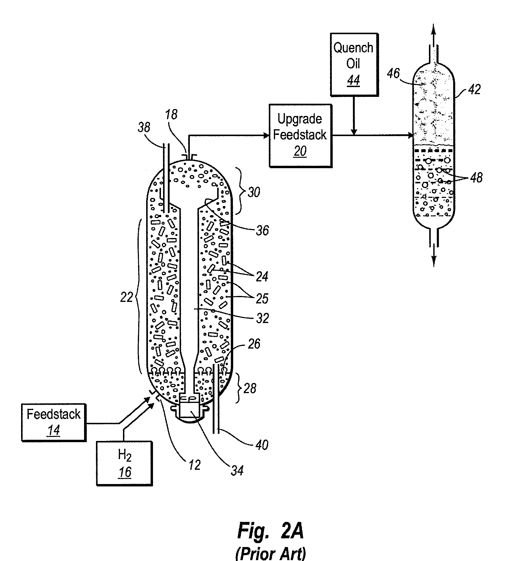
[0018]Conventional ebullated bed hydroprocessing systems typically include one or more ebullated bed reactors that comprise a reaction chamber, a port at the bottom of the reaction chamber through which a heavy oil feedstock and pressurized hydrogen gas are introduced, a port at the top of the reaction chamber through which fresh catalyst is introduced, a recycle cup and conduit in the center of the reaction chamber, an expanded catalyst zone, an ebullating pump that circulates the reactor liquid down through the recycle cup and conduit and up through the expanded catalyst zone, a first catalyst free zone at the reactor bottom (or plenum), a second catalyst free zone above the expanded catalyst zone, a port at the top of the reaction chamber through which an upgraded feedstock is withdrawn from the second catalyst free zone, and a port at the bottom of the reaction chamber through which spent catalyst is withdrawn. Circulation of the heavy oil feedstock upwards through the expanded catalyst zone maintains the solid supported catalyst in an expanded, or fluidized state. It also helps equalize the temperature of the feedstock throughout the reaction chamber.

Problems solved by technology

Unfortunately, heavy oil molecules within the feedstock can continue undergoing thermal cracking reactions in the catalyst free zones so as to form free radicals that have the potential of reacting with other free radicals to produce coke precursors and sediment within the ebullated bed reactor and / or within downstream processing equipment.
Likewise, larger molecules that are too large to diffuse into the pores of the ebullated bed catalyst.
Moreover, asphaltenes and / or other heavy oil molecules that are too large to enter the pores of the supported catalyst can form coke precursors and sediment even within the expanded catalyst zone, potentially fouling and / or prematurely deactivating the catalyst (e.g., by plugging the pores of the catalyst and / or agglomerating porous supported catalyst particles together to form catalyst balls).
For the foregoing reasons, it is very difficult to upgrade heavy oil feedstocks rich in asphaltenes (e.g., vacuum tower bottoms) using conventional ebullated bed hydroprocessing systems because they tend to quickly foul and / or deactivate such systems.

Method used


Image

  • Ebullated bed hydroprocessing systems
  • Ebullated bed hydroprocessing systems
  • Ebullated bed hydroprocessing systems

Examples


example 1

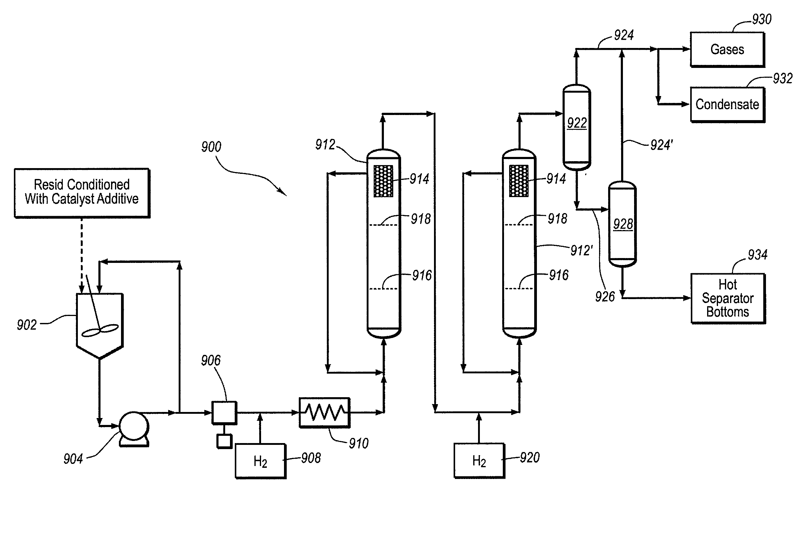
[0145]The ability of a colloidal or molecular catalyst and a porous supported catalyst to convert the asphaltene fraction of a heavy oil feedstock was compared. A heavy oil feedstock comprising Cold Lake bitumen atmospheric resid and 300 ppm of a molybdenum disulfide catalyst in colloidal or molecular form was introduced into a pilot slurry phase hydroprocessing reactor system and operated at various percent resid conversion levels. The pilot reactor system used in this test was similar to that shown in FIG. 10 (discussed more fully below), except that the pilot reactor system only had a single continuous flow slurry phase reactor having a volume of 1200 ml. The pilot reactor was a hollow tube and had no internal liquid recycle system. The pilot plant experiments were carried out under 2000 psig of hydrogen pressure, with a reaction temperature over the range of 430-450° C. to control the conversion level and a hydrogen flow rate of 5000 standard cubic feet per barrel of heavy oil (...

example 2

[0149]A heavy oil feedstock comprising Athabasca vacuum tower bottoms (which included 21 wt. % of pentane insoluble asphaltenes) from the Syncrude Canada Ltd. plant in Alberta, Canada, with 150 ppm of a molybdenum sulfide catalyst in colloidal or molecular form was introduced into a pilot plant similar to the one shown in FIG. 10 having two gas-liquid slurry phase reactors connected in series. Each reactor had a volume of 2200 ml. The first reactor was heated to a weighted averaged temperature below 370° C. (698° F.), and the second reactor was heated to a weighted averaged temperature between 419-445° C. (786-833° F.) and liquid hourly space velocity between 0.41 and 0.7 / hr. The results of this test showed that the concentration of the asphaltene in the residual resid at 75% conversion was also 21 wt. %, which was identical to that in the original feedstock, thereby further confirming the ability of the colloidal or molecular catalyst to convert the asphaltene fraction at the same ...

example 3

[0150]This example tested the ability of a colloidal or molecular catalyst utilized in a slurry phase reactor according to the invention to convert various resid materials and their asphaltene and sulfur fractions at high conversion rates. The pilot plant used in this example was the same slurry phase, tubular reactor described in Example 1. In each test, the heavy oil feedstock was thoroughly mixed with up to 250 parts per million of the catalyst precursor over a prolonged period of time before being introduced to the reactor. The reactor temperature was maintained between 430-450° C. to control the conversion level. The reactor pressure was 2000 psig and the hydrogen treat rate was 5000 standard cubic feet per barrel of heavy oil. The results of this test are set forth in Table I below:

TABLE IColdMaya / AthabascaLakeIsthmusChinese ParaffinicFeedstockBitumenBottomsBlendBottoms Blend975° F. + resid94946395conversion, wt %Asphaltene (C5 Ins.)95936796conversion wt %Sulfur conversion7878...


PUM

PropertyMeasurementUnit
boiling pointaaaaaaaaaa
temperaturesaaaaaaaaaa

Abstract

An ebullated bed hydroprocessing system, and also a method for upgrading a pre-existing ebullated bed hydroprocessing system, involves introducing a colloidal or molecular catalyst, or a precursor composition capable of forming the colloidal or molecular catalyst, into an ebullated bed reactor. The colloidal or molecular catalyst is formed by intimately mixing a catalyst precursor composition into a heavy oil feedstock and raising the temperature of the feedstock to above the decomposition temperature of the precursor composition to form the colloidal or molecular catalyst in situ. The improved ebullated bed hydroprocessing system includes at least one ebullated bed reactor that employs both a porous supported catalyst and the colloidal or molecular catalyst to catalyze hydroprocessing reactions involving the feedstock and hydrogen. The colloidal or molecular catalyst provides catalyst in what would otherwise constitute catalyst free zones within the ebullated bed hydroprocessing system. Asphaltene or other hydrocarbon molecules too large to diffuse into the pores of the supported catalyst can be upgraded by the colloidal or molecular catalyst. A slurry phase reactor may be positioned upstream from one or more ebullated bed reactors or converted from a pre-existing ebullated bed reactor.

Description

CROSS-REFERENCE TO RELATED APPLICATIONS[0001]This application is a division of co-pending U.S. patent application Ser. No. 11 / 117,202, filed Apr. 28, 2005, which claims the benefit under 35 U.S.C. § 119 of U.S. Provisional Application No. 60 / 566,335, filed Apr. 28, 2004, and also U.S. Provisional Application No. 60 / 566,268, filed Apr. 28, 2004, the disclosures of which are incorporated herein in their entirety.BACKGROUND OF THE INVENTION[0002]1. The Field of the Invention[0003]The invention involves methods and systems for hydroprocessing heavy oil feedstocks that include a significant quantity of asphaltenes and fractions boiling above 524° C. (975° F.) to yield lower boiling, higher quality materials. The invention specifically relates to ebullated bed hydroprocessing methods and systems that employ a colloidal or molecular catalyst and a porous supported catalyst, and methods for upgrading an existing ebullated bed system, so as to be better suited for upgrading lower quality fee...

Claims


Application Information

Patent Timeline
Patent Type & Authority Applications(United States)
IPC IPC(8): B01J19/00C10G45/00C10G47/00C10G47/26
CPCB01J8/226C10G47/26C10G65/02C10G67/08C10G2300/1033C10G49/005C10G2300/1077C10G2300/206C10G2300/703C10G2300/802C10G2300/107C10G45/04C10G45/16C10G45/34C10G45/46C10G45/56C10G47/06C10G49/12C10G65/00C10G2300/202C10G2300/4056C10G2300/70C10G47/02B01J8/08B01J8/22
Inventor LOTT, ROGER K.LEE, LAP-KEUNG
Owner HEADWATERS TECH INNOVATION LLC
Why Eureka
Try Eureka