
Progressive Grip Assembled Bone-Tendon-Bone Grafts, Methods of Making, and Methods of Use

a technology of tendon-bone grafts and progressive grip, which is applied in the field of bone-tendon-bone implants, grafts, and components, can solve the problems of increasing procedure time and operation costs, requiring the creation of second morbidity sites, and patients often complaining of pain and resultant effects, etc., and achieves the effect of improving performan

Active Publication Date: 2008-08-14
RTI BIOLOGICS INC
View PDF17 Cites 44 Cited by
  • Summary
  • Abstract
  • Description
  • Claims
  • Application Information

AI Technical Summary

Benefits of technology

[0027]It is also within the scope of the invention that the bone components used in implants of the present technology may be made of artificial bone, by which is meant natural or synthetic materials including metals, ceramics polymers, composites or combinations thereof which exhibit properties similar to cortical bone. Commonly known examples are Poly L-Lactic Acid (PLLA) or calcium phosphate or hydroxyapatite based materials. These are available from various manufacturers such as U.S. Biomaterials, Alachua, Fla. and OsteoBiologics, Inc. (OBI), San Antonio, Tex. Artificial or natural bone constructs may also be enhanced by the addition of cultured autologous or allograft or xenograft cells or genetically modified cells which support bone growth and healing by the presence of or expression of growth factors, hormones, or cell lines involved in the healing process. Any cells added to the artificial or natural bone constructs may be selected, treated, genetically modified, processed or otherwise engineered to reduce negative effects such as antigencity, inflammation, rejection, or immune response by or against the host.
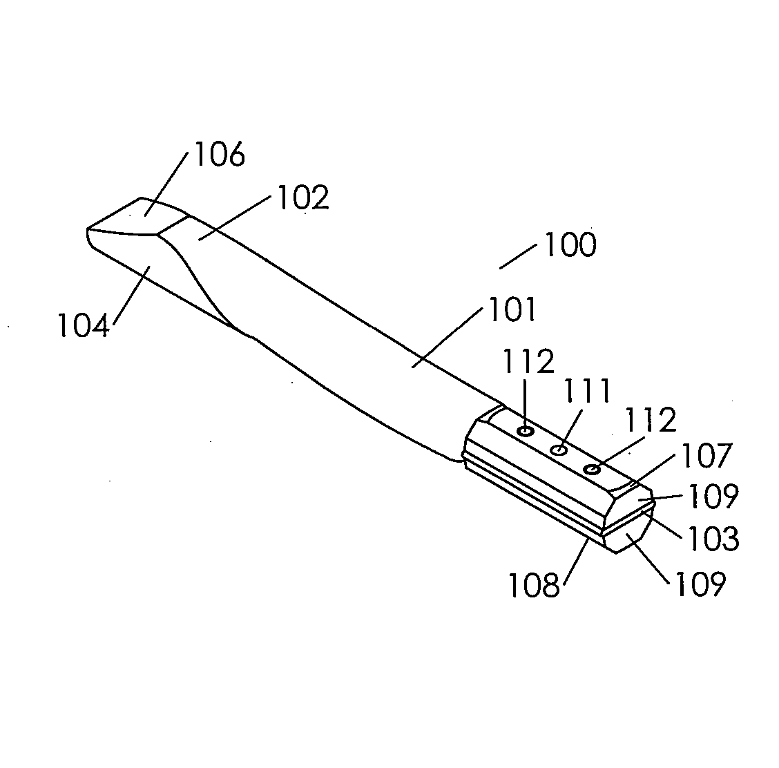
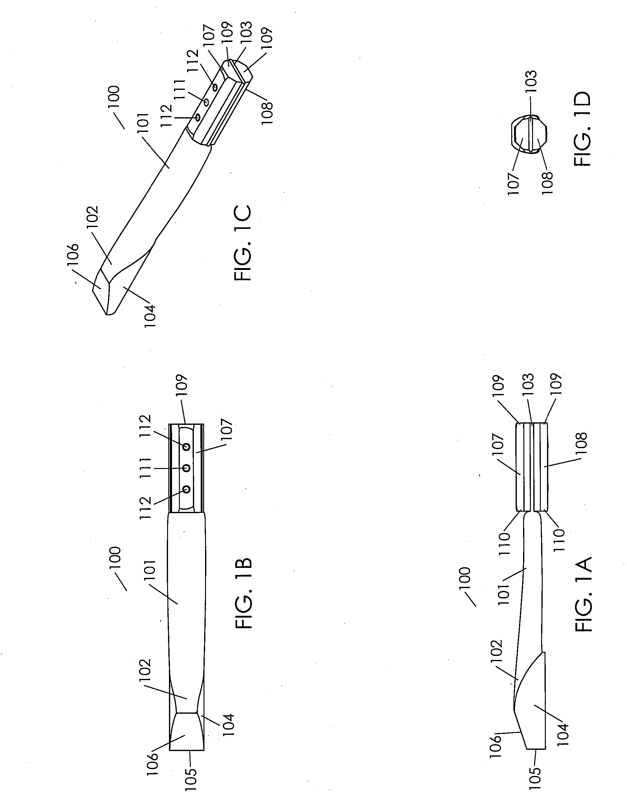
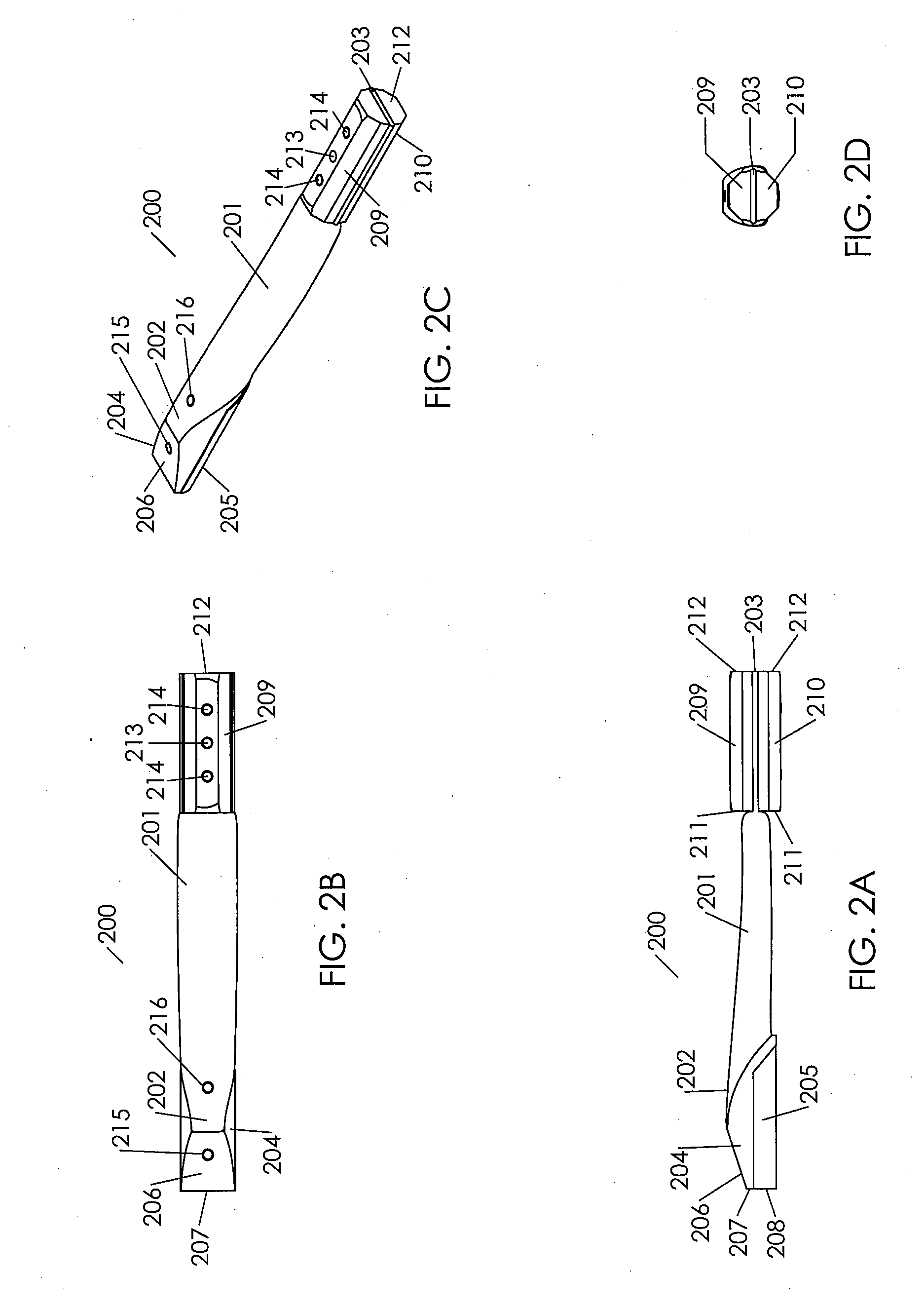
[0029]It has been surprisingly discovered that assembled implants that grip a tendon can have improved performance when they are designed and configured such that the nature of the grip on the tendon changes from its pre-implantation state to its post-implantation state, while the general location and orientation of the bone block assemblies relative to the tendon is maintained at about the same position in at least one dimension. Accordingly, in one aspect, the present technology relates to an implant comprising a tendon and a bone block assembly comprising at least a first intermediate bone block and a second intermediate bone block, wherein the bone block assembly has a first grip on the tendon prior to implantation of the implant into a patient and a second grip on the tendon after implantation of the implant into a patient.

Problems solved by technology

However, use of autograft materials is attended by the significant disadvantage that a second site of morbidity must be created to harvest autograft for implantation into the diseased or injured site.
Patients often complain about the pain and resultant effects at the harvest site.
Additionally, the use of autograft materials increases procedure time and operation costs, as well as increasing the physician risk due to the handcrafting and judgment oriented aspects involved in harvesting and shaping an implant in the operating room.
Human allograft materials have the disadvantage of being frequently low in availability and high in cost of recovery, treatment and preparation for implantation.
Certain highly desirable tissue types such as tendon allografts in general and bone-tendon or bone-tendon-bone grafts in particular face long standing and significant supply shortages.
Demand for such tissues is difficult to measure definitively, but is believed to be at least about two to three times historically available levels of supply.
Such xenograft materials are readily available, but the actual use of such materials is significantly constrained due to immunological, regulatory, and disease transmission considerations and restrictions.
Further, due to differences in size, structure and anatomy between species, it is sometimes difficult to locate a properly suited xenograft bone-tendon-bone implant.
However, this technique is often not possible, especially when the damage to the ligament is extensive.
One shortcoming of such procedures involving reconnection or redirection of tendons is that the repaired joint tends to lack flexibility and stability.
Despite the realized advantages associated with bone-tendon-bone grafts, there have been some difficulties encountered with utilizing currently available bone-tendon-bone grafts.
One problem with such a device is that the screw, although bio-compatible, will never become assimilated into the patient's body and will not be remodeled over time.
A second problem is that the tendon or ligament will never form a natural attachment to the screw.
One shortcoming of this approach is that it is difficult to pull a predetermined tension on the tendon because the tendon slips in the bone tunnel and uncontrollably alters the tension when the interference screw is being threaded in the bone tunnel.
The slippery ligament is also subject to slippage when compressed between the bone block and the tunnel wall.
Such slippage results in a loss of tension in the joint.
In the case of an ACL repair, this loss of tension causes a wobbly knee.
A second shortcoming of this method is an increase in complexity, difficulty, and time required during implantation, as the components are not pre-attached and do not have any predetermined position along the length of the tendon prior to implantation.
This is undesirable in any human, and particularly in athletes.
This can lead to impaired healing and recovery due to tendon to bone contact within the tunnel and also due to micromotions of the tendon within the tunnel.
Ultimately, this may lead to widening of the bone tunnels rather than their closure.
Additionally, the location of the tendon in the locking grooves is a function of the anchor body design and is not a controlled design parameter.
Thus, the tendon placement with respect to either the tunnel wall or the tunnel centerline cannot be matched to particular surgical needs or to surgeon preference.
Further, there is an increase in complexity, difficulty, and time required during implantation, as the components are not pre-attached and do not have any predetermined position along the length of the tendon prior to implantation.
One shortcoming of this design is the very large amount of contiguous cancellous bone required to construct the bone blocks.
Cancellous bone material is costly, as well as being in high demand and short supply.
This presents a conflict between the need to maintain the size of the bone tunnel drilled in the patient's leg, the need to provide a large enough tendon to support the loads required for successful recovery and physical therapy, and the need to provide sufficient cancellous material for structural support and fixation.
While all of these embodiments are potentially useful, they each are challenging to manufacture and / or assemble due to their inherent complexity and reliance on small or intricate parts.
The availability of such implants can be limited due to the limited quantity of undamaged material sources and the age requirements that are acceptable to physicians.
Frequently, this leads to compromises such as excessive gauge length (length between the bone blocks), which result in surgical challenges and compromised healing and recovery.
For example, a natural BTB with a tendon that is too long for an ACL repair results in having a length of unsecured and wobbling tendon in the bone tunnel between the ends of the secured bone portions.
The wobbling tendon hinders healing in the bone tunnel.
The making of BTB implants in this manner increases time spent in the operating room per procedure, which increases procedure costs, and can result in increased surgeon risk due to the fact that the surgeon is individually handcrafting each implant.

Method used


Image

  • Progressive Grip Assembled Bone-Tendon-Bone Grafts, Methods of Making, and Methods of Use
  • Progressive Grip Assembled Bone-Tendon-Bone Grafts, Methods of Making, and Methods of Use
  • Progressive Grip Assembled Bone-Tendon-Bone Grafts, Methods of Making, and Methods of Use

Examples


examples

[0171]Sample BTB implants were made and tested in accordance with the following procedures:

Static Testing: (Test Substrate: porcine tibias)

[0172]All static testing was conducted on an Instron testing machine. Each Sample BTB implant was statically pretensioned for 15 minutes to 90 N at three, 5 minute intervals. Each Sample BTB implant was dynamically preconditioned after the specimen had been pretensioned. The Sample BTB implant was relaxed to 30N for 30 seconds and then preconditioned for 15 cycles from 30N to 150N at 1 Hz. Immediately following dynamic preconditioning the specimen was pulled to failure at a rate of 50 mm / min.

[0173]During static pretensioning, data was recorded for load in Newtons and displacement in mm at an interval of 2N or every 1 second. During dynamic preconditioning and pull to failure, data was collected at an interval of 2N or every 0.05 seconds.

Dynamic Test: (Test Substrate: 20 lb / ft̂3 Structural Foam, Sawbones Catalog Number 1522-03, Pacific Research La...


PUM


Abstract

The present technology is related to the field of bone-tendon-bone implants, grafts, and components thereof, for implantation in mammals, particularly for implantation in humans. More particularly, the present technology relates to assembled implants that comprise a length of tendon and at least two bone components or intermediate bone blocks that are assembled to form a bone-tendon-bone implant, and methods of making such implants. In some embodiments, implants of the present technology provide a first grip on the tendon prior to implantation and a second grip during or after implantation. In some embodiments, bone block assemblies or intermediate bone blocks of the present technology have a first geometric configuration prior to implantation and a second geometric configuration during or after implantation.

Description

RELATED APPLICATIONS[0001]Not ApplicableFEDERALLY SPONSORED RESEARCH OR DEVELOPMENT[0002]Not ApplicableMICROFICHE / COPYRIGHT REFERENCE[0003]Not ApplicableFIELD OF THE INVENTION[0004]The present technology generally relates to the field of bone-tendon-bone implants, grafts, and components thereof, for implantation in mammals, particularly for implantation in humans.BACKGROUND OF THE INVENTION[0005]In the field of medicine, there has been an increasing need to develop implant materials for correction of biological defects. Particularly, in the field of orthopedic medicine, there has been the need to replace or correct bone, ligament and tendon defects or injuries. For example, Anterior cruciate ligament (ACL) reconstruction has become a common orthopedic procedure, with more than 200,000 ACL reconstructions being performed annually in the United States. The number of procedures involving the replacement, repair, or reconstruction of other tendons and ligaments is also increasing.[0006]...

Claims


Application Information

Patent Timeline
Patent Type & Authority Applications(United States)
IPC IPC(8): A61F2/08A61F2/02A61B17/56
CPCA61F2/08A61F2/0811A61F2002/0888A61F2002/0835A61F2002/0864A61F2002/0829
Inventor ZHUKAUSKAS, ARUNAS A.GOEDE, TODD E.SCHMITT, ERIC J.BROWN, LAUREN M.GROVER, GUY B.BURSAC, PREDRAGSANDERS, BEN R.
Owner RTI BIOLOGICS INC
Learn More