Method to limit a creep of bolts and gaskets of bolted flanged connections

a bolt and flange connection technology, applied in the direction of threaded fasteners, machines/engines, washing machines, etc., can solve the problems of gasket damage and failure, complex structural integrity of the bfcs and plant/piping operation leakage reduction, and cost each process industry hundreds of millions of dollars annually in lost profits. , to achieve the effect of maximizing the efficiency of critical technological equipment and increasing the bfc leak-tightness

Inactive Publication Date: 2008-08-21
EFREMOV ANATOLY
View PDF7 Cites 2 Cited by
  • Summary
  • Abstract
  • Description
  • Claims
  • Application Information

AI Technical Summary

Benefits of technology

[0034]A principal advantage of the present invention is a new approach to the sealing technology based on “active” intervention of bolts and gaskets of the BFCs into technological processes by means of bolts and gaskets manufactured from SMAs having temperature intervals of reverse martensitic phase transformation close to operational temperatures of the BFCs.
[0035]Another advantage of the present invention consists in the use of reactive shape-recovering stresses generated by constrained recovery of shape-memorized deformations of the bolts and gaskets manufactured from SMAs and shape-memorized to the compression (bolts) and “swelling” (gaskets). The reactive shape-recovering stresses appear under operational temperatures of the BFCs providing the “negative creep” effect that limits or excludes operational creep of the bolts and gaskets.
[0036]It is a next advantage of the present invention to provide a continuous automatic tight contact between flange and gasket surfaces under critical operational conditions including high internal pressures and a variety of operational temperatures. This contact is provided by constrained shape recovery of the gasket thickness of SMA that is shape-memorized to the “swelling”. Reactive shape-recovering stresses due to constrained recovery of initial thickness of the gasket ensure this contact that significantly increases a leak-tightness of the BFC and maximizes efficiency of critical technological equipment.

Problems solved by technology

There are millions of bolts and gaskets used in critical engineering structures, and the problem of the BFCs' structural integrity and plant / piping operational leakage reduction is very complex and involves many areas of applied mechanics and technological findings.
Safe design of the BFCs from structural integrity point of view has been satisfactorily solved and standardized, but the leakage events remain an unresolved problem and a principal cause of bolt and / or gasket damages and failure that are attributed to the high level of corrosion combined with high level of stresses and strains due to cyclic internal pressures, external loadings, elevated operational temperatures, flow-induced vibrations, integral flow of neutrons, and other critical factors.
Statistic data show that, for example, piping system leakages alone conservatively cost each process industry hundreds millions of dollars annually in lost profits as a result of plant shutdowns, production penalties, maintenance rework activities, equipment repair or replacement, and so on.
One of the main causes of plant / piping leakages is a “passive” behavior of bolts and gaskets under critical operational conditions when nonlinear gasket response to the loading-unloading processes combined with creep of bolt and gasket materials lead to clamping force decrease and unavoidable joint opening followed by leakages.
Generally, creep is accompanying by stress relaxation, and elongation of the bolts along with contraction of the gasket due to creep-relaxation is a very serious problem because it lead to bolt load and gasket stress losses that, in turn, increase the leakage rate.
A plant maintenance practice includes periodical retightening or replacement of the bolts and gaskets subjected to creep-relaxation to prevent leakages, and, having in mind a great quantity of bolts and gaskets used in critical industries, the procedure involves an expensive time-consuming process, but it provides only temporary effect because the creep-relaxation increases rapidly after each additional retightening and the risk of leakage event relatively increases.
Nevertheless, during the development of most design procedures, a little consideration has been given to operational creep-relaxation of the bolts and gaskets, and similar situation is observed with patent documents.
U.S. Pat. No. 6,199,453 by Steinbock entitled “High temperature bolting system” offers a sophisticated apparatus for maintaining a clamping bolt force between component parts of a steam turbine while operating at temperatures from 800° F. to 1200° F. However, the disclosed elongated stepped fastener shank manufactured from superalloy Inconel 718 having a thermal expansion coefficient similar to flange material cannot stop a creep-relaxation process and protect proposed bolting system from creep-relaxation that is an increase of bolt elongations and decrease of bolt stresses with time.
Moreover, the combination of high level of stresses and temperatures will induce the high level of creep-relaxation of the bolts that defines their routine “passive” behavior under critical operational conditions.
However, these super characteristics did not exclude the creep-relaxation from 20% to 30% in dependence on thickness of proposed tested materials.
The most important failing however is the fact that proposed gasketing materials copy a typically used approach to the fabrication of any known sealing materials based on their traditional “passive” behavior under critical operational conditions.
Additionally, the bolt fabrication procedure is based on compression of the bolt under high temperature of austenite state that increases a risk of the bolt's buckling.

Method used


Image

  • Method to limit a creep of bolts and gaskets of bolted flanged connections
  • Method to limit a creep of bolts and gaskets of bolted flanged connections
  • Method to limit a creep of bolts and gaskets of bolted flanged connections

Examples


Embodiment Construction

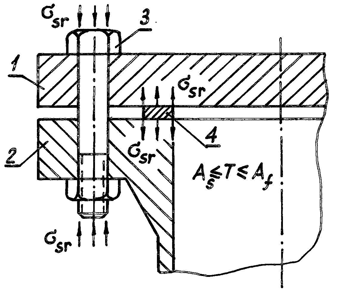
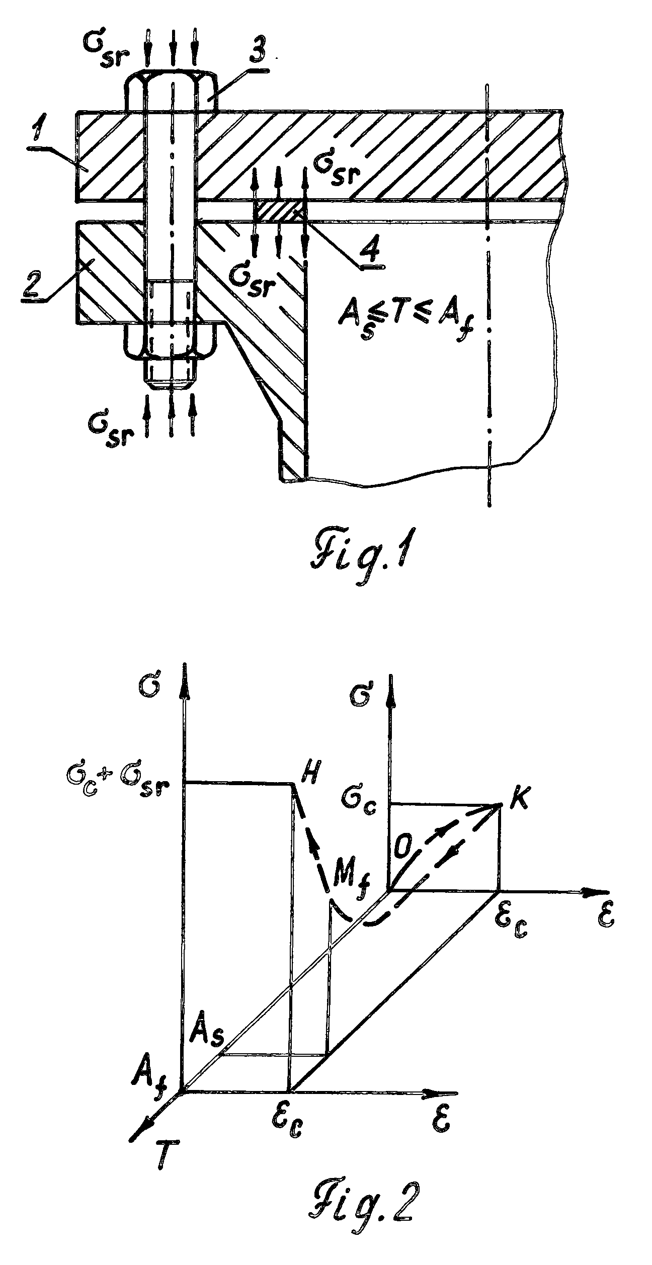
[0041]FIG. 1 is a cross-sectional view of a part of BFC having the flanges 1 and 2 of conventional structural steel, and bolts 3 and gasket 4 manufactured from the same SMA having temperature interval As≦T≦Af of reverse martensitic phase transformation that is close to operational temperatures of the BFC. Bolts and gasket are shape-memorized to the compression (bolts) and “swelling” (gasket). The constrained shape recovery of stretched bolts and compressed gasket at temperature interval As≦T≦Af produces reactive shape-recovering stresses σsr having direction inverse to the direction of operational creep of the bolts and gasket. Hence, FIG. 1 illustrates a main principle of “negative creep” effect that limits or excludes elongation of the bolts and contraction of the gasket due to their operational creep under temperature interval As≦T≦Af of the BFC.

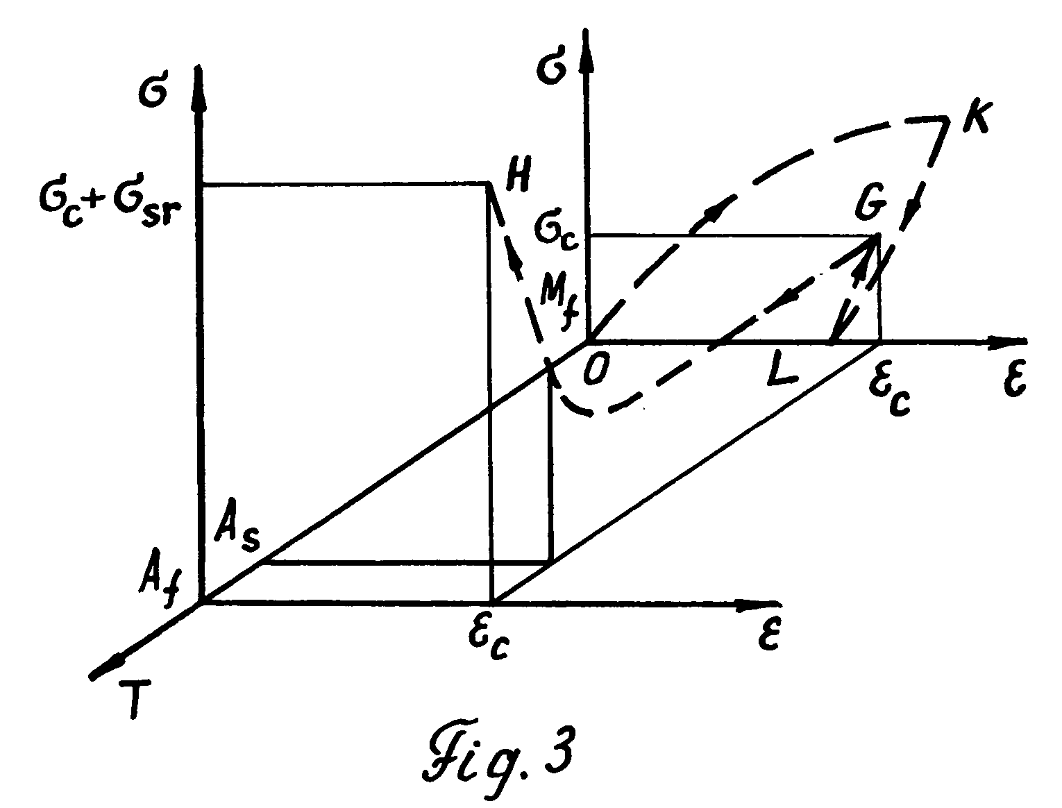
[0042]FIG. 2 is a schematic representation of constrained shape recovery of the bolt of SMA that is stretched by bolt preload force from...


PUM


Abstract

A method to limit or exclude operational creep of the bolts and gaskets of Bolted Flanged Connections (BFCs) is disclosed. The method consists in the use of bolts and gaskets manufactured from the same Shape Memory Alloys (SMAs) having temperature intervals of reverse martensitic phase transformation close to operational temperatures of the BFCs. These bolts and gaskets of the BFCs are shape-memorized to the compression (bolts) and “swelling” (gaskets) during (1) the formation of stress-induced martensite under temperature of martensite state of the SMAs while bolt preload application, or (2) during the formation of stress-induced martensite while loading-unloading previously stretched bolts and previously compressed gaskets under temperature of martensite state resulting in residual bolt elongations and residual gasket contraction followed by bolt preload application. Constrained shape recovery of initial length of the bolts and initial thickness of the gaskets under operational temperatures of the BFCs is accompanying by appearance of reactive shape-recovering stresses having direction inverse to the direction of operational creep of the bolts and gaskets that limits or excludes their operational creep.

Description

CROSS-REFERENCE TO RELATED APPLICATIONS[0001]This Patent Application is continuation of earlier provisional patent application Ser. No. 60 / 925,840 filed Apr. 24, 2007, and patent application Ser. No. 10 / 834,955 filed Apr. 30, 2004 now abandoned.FEDERALLY SPONSORED RESEARCH [0002]NoneSEQUENCE LISTING OR PROGRAM [0003]NoneBACKGROUND OF THE INVENTION[0004]1. Field of the Invention[0005]This invention relates to Bolted Flanged Connections (BFCs) with gaskets as sealing elements that must provide a leak-tight and durable joint between component parts of the pressure vessels, piping systems, and other engineering structures that operate under conditions of internal pressures and a variety of operational temperatures.[0006]2. Background of the Invention[0007]One of the most typical means to obtain a leak-tight and durable joint between component parts of boilers, reactors, steam generators, piping systems, and other engineering structures is an assemblage of their pieces with the BFCs. The...

Claims


Application Information

Patent Timeline
Patent Type & Authority Applications(United States)
IPC IPC(8): F16B1/00F02F11/00F16B33/00F16B43/00F16L23/20
CPCF16B1/0014F16B33/006F16B43/00Y10S411/909Y10T403/645Y10T403/21Y10T403/217F16L23/20F16B2200/506F16B2200/77
Inventor EFREMOV, ANATOLY
Owner EFREMOV ANATOLY
Why Eureka
Try Eureka