
Split-cycle engine with water injection

Inactive Publication Date: 2008-08-28
SKADERI GRUP LLC
View PDF20 Cites 86 Cited by
  • Summary
  • Abstract
  • Description
  • Claims
  • Application Information

AI Technical Summary

Benefits of technology

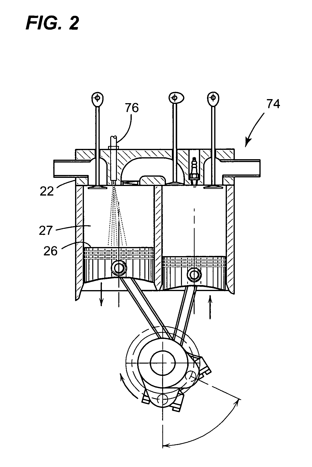
[0013]Water injection into the compressor cylinder is predicted to increase brake power and efficiency. Water injection into the crossover passage may have no power or efficiency benefits, but may significantly reduce NOx and detonation effects. It is assumed that any added water is heated externally using a form of waste heat.
[0014]Steam injection into the compressor cylinder is predicted to have neutral effects, but steam injection into the crossover passage should increase engine power and efficiency. It is assumed that any added steam is generated externally using waste heat.
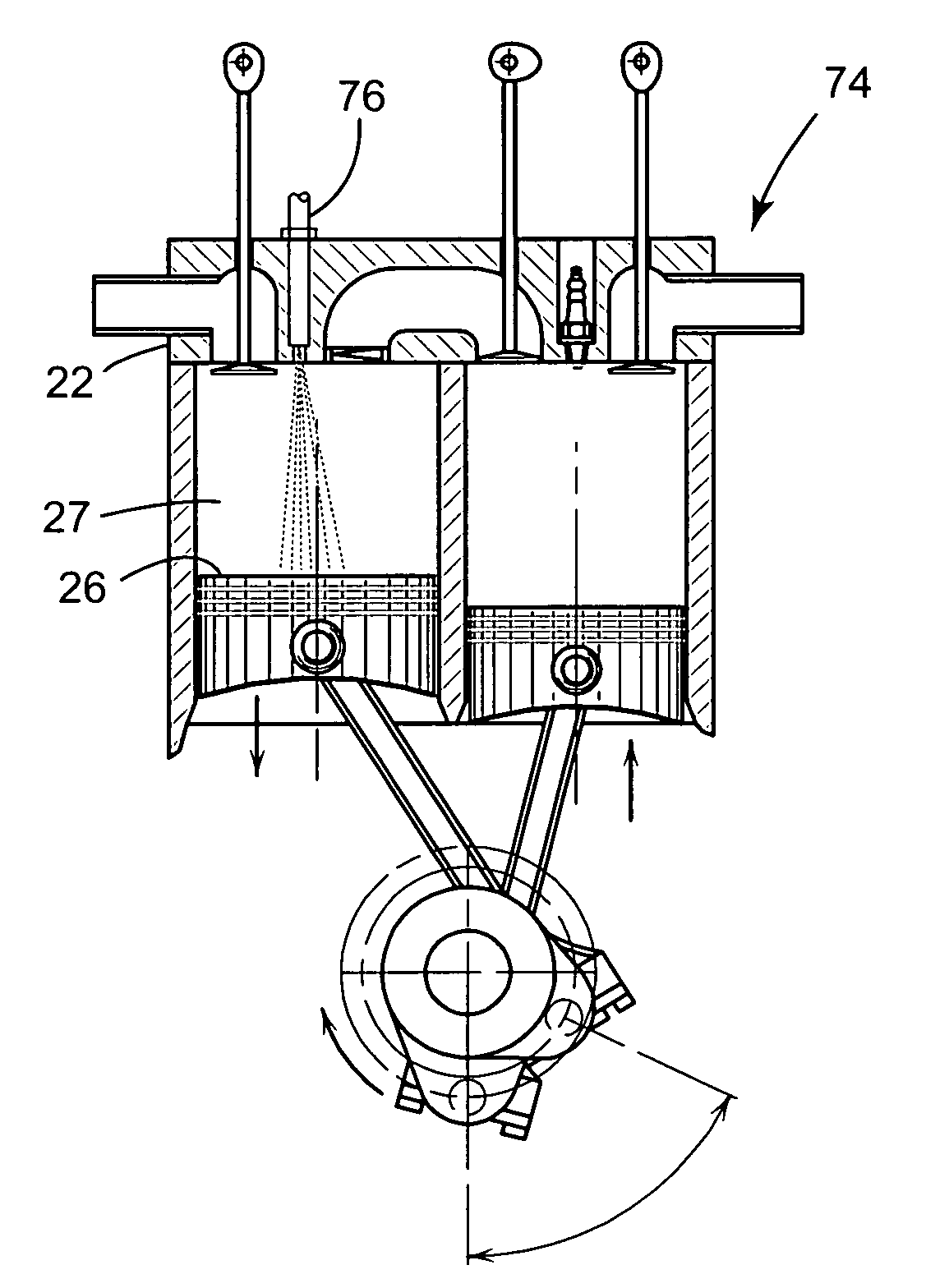
[0015]Water injection into the expansion cylinder is predicted to significantly improve both brake power and efficiency if the injected water can be made to impinge on the piston or cylinder head in order to generate steam while cooling those parts of the engine.
[0018]While benefits of water or steam injection appear attractive, there are serious practical issues, notably added hardware complexity, water consumption, freezing protection, oil contamination and possibly corrosion. External steam generation would be a major hardware cost. On the other hand, the split cycle engine stands to gain more from water injection to the compressor than a 4-stroke engine, because the compressor work, and re-expansion losses, are greater than a 4-stroke engine. Although steam injection may be difficult in the expansion cylinder, it may be easier in the crossover passage and could help control crossover wall temperatures.

Problems solved by technology

Water injection into the crossover passage may have no power or efficiency benefits, but may significantly reduce NOx and detonation effects.

Method used


Image

  • Split-cycle engine with water injection
  • Split-cycle engine with water injection
  • Split-cycle engine with water injection

Examples


Embodiment Construction

I. Overview

[0043]The Scuderi Group LLC commissioned the Southwest Research Institute® (SwRI®) of San Antonio, Tex. to perform a Computerized Study. The Study involved constructing computer models used in determining predicted effects on operation of a split-cycle four stroke engine of the direct injection of water and / or steam into the compression cylinder, the crossover passage or the expansion cylinder of the engine. The Computerized Study resulted in the present invention described herein through exemplary embodiments pertaining to a split-cycle engine.

II. Glossary

[0044]The following glossary of acronyms and definitions of terms used herein is provided for reference.[0045]ATDC: After Top Dead Center;[0046]Auto-ignition: uncontrolled ignition of part of the air / fuel mixture prior to controlled ignition initiated by the spark plug;[0047]Bar: unit of pressure, 1 bar=0.1 N / mm2;[0048]Baseline: GT Power model status established in U.S. Pat. No. 6,952,923 and used as a baseline for late...


PUM


Abstract

A split-cycle water injection engine includes a crankshaft rotatable about a crankshaft axis. A power piston is slidably received within a power / expansion cylinder and operatively connected to the crankshaft. A compression piston is slidably received within a compression cylinder and operatively connected to the crankshaft. A crossover passage is operatively connected between the compression cylinder and the power / expansion cylinder and selectively operable to receive compressed air from the compression cylinder and to deliver compressed air to the power / expansion cylinder for use in transmitting power to the crankshaft during engine operation. Valves selectively control gas flow into and out of the compression and power cylinders. A water injector is associated with and adapted to inject water into at least one of the compression cylinders the crossover passage and the power cylinder during engine operation.

Description

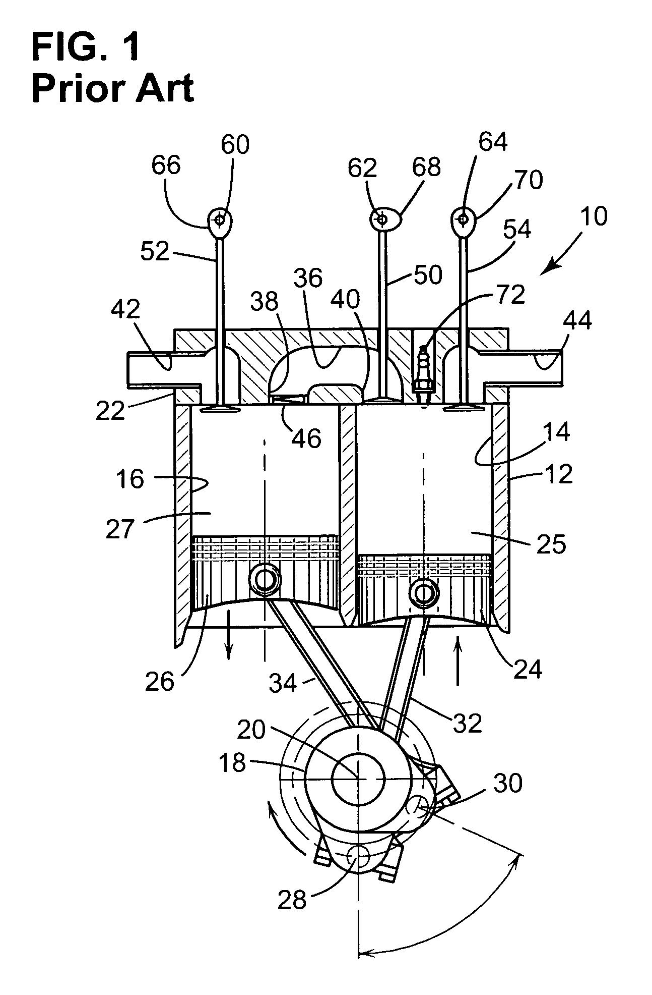
CROSS REFERENCE TO RELATED APPLICATION[0001]This application claims the benefit of U.S. Provisional Application No. 60 / 903,640, filed Feb. 27, 2007.TECHNICAL FIELD[0002]This invention relates to split-cycle engines and, more particularly, to such engines incorporating water injection for improved power and / or operation.BACKGROUND OF THE INVENTION[0003]For purposes of clarity, the following definition is offered for the term split-cycle engine as may be applied to engines disclosed in the prior art and as referred to in the present application.[0004]A split-cycle engine as referred to herein comprises:[0005]a crankshaft rotatable about a crankshaft axis;[0006]a power piston slidably received within a power cylinder and operatively connected to the crankshaft such that the power piston reciprocates through a power (or expansion) stroke and an exhaust stroke during a single rotation of the crankshaft;[0007]a compression piston slidably received within a compression cylinder and operati...

Claims


Application Information

Patent Timeline
IPC IPC(8): F02B75/18F02B47/02
CPCF02B21/00F02B33/22F02B33/30F02B33/44F02B47/02F02M25/038F02M25/03F02M43/00Y02T10/121F02M25/0227F02B47/06Y02T10/12F02B75/12F02M25/025
Inventor PIRAULT, JEAN-PIERRE
Owner SKADERI GRUP LLC
Learn More