
Macroscopic ordered assembly of carbon nanotubes

a carbon nanotube and ordered assembly technology, applied in the manufacture of electrical systems, magnetic materials, energy-based chemical/physical/physicochemical processes, etc., can solve the problems of difficult separation of individual carbon nanotubes from the other reaction products, low nanotube yield, and significant variation in structure and siz

Inactive Publication Date: 2008-09-04
RICE UNIV
View PDF9 Cites 35 Cited by
  • Summary
  • Abstract
  • Description
  • Claims
  • Application Information

AI Technical Summary

Benefits of technology

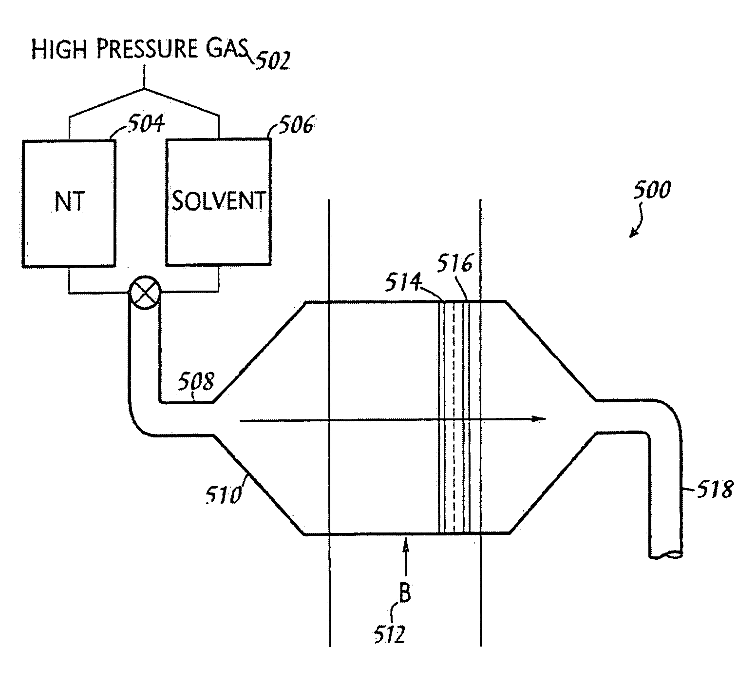
[0027]It is a technical advantage of the present invention that a method for chemical manipulation of single-wall carbon nanotubes that enables production of large ropes and a macroscopic ordered assembly of carbon nanotubes is disclosed.
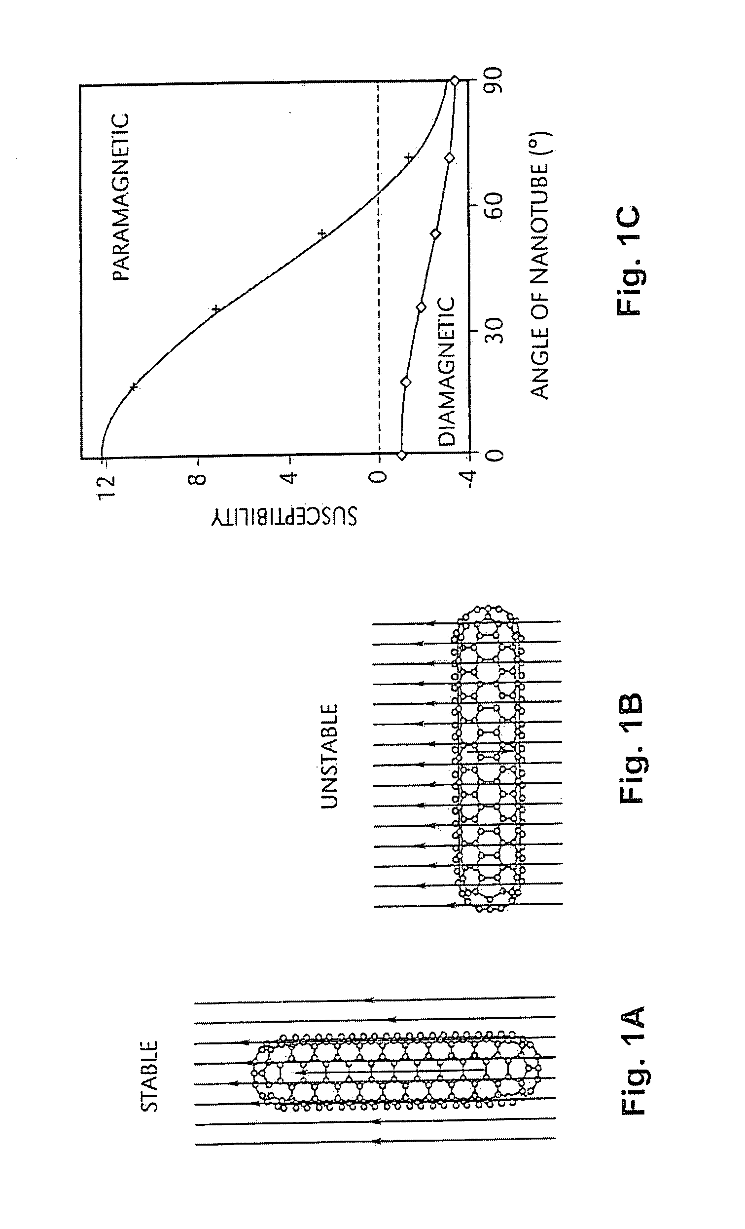
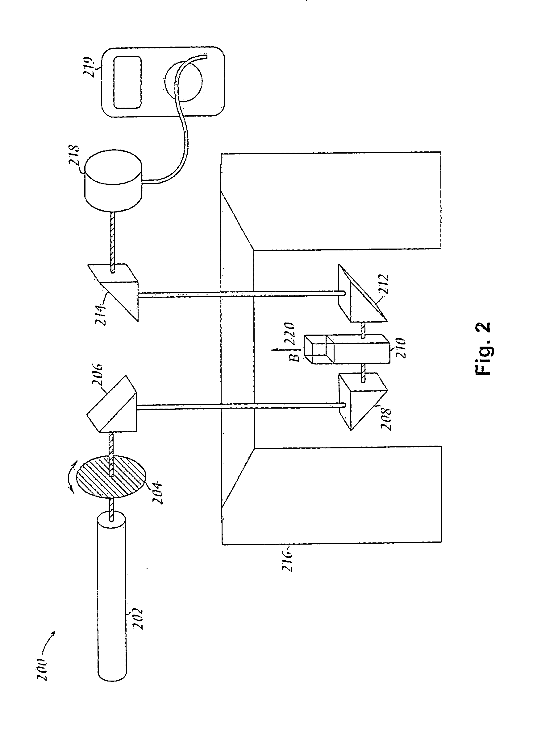
[0028]It is technical advantage of the present invention that a method for magnetic manipulation of single-wall carbon nanotubes and ropes is disclosed
[0029]It is a technical advantage of the present invention that methods for producing a macroscopic ordered assembly of carbon nanotubes are disclosed. It is a technical advantage of the present invention that methods for post processing a macroscopic ordered assembly of carbon nanotubes that modify the properties of said assembly and are fundamentally enabled by the assembly's structure are disclosed.
[0030]The foregoing objectives, the compositions of matter produced by them and other objectives apparent to those skilled in the art, are achieved according to the present invention as described and claimed herein.
[0031]The ordered assemblies also are important in their service as a substrate for initiation of growth of more and larger ordered assemblies of nanotubes. Here, the ordered assembly is cut in a direction perpendicular to that of the tube axes. The exposed surface is then cleaned and made uniform using electrochemical polishing or other means known to those skilled in the art of surface science. A transition metal catalyst is placed on or near the open tube ends. The catalyst is either in the form of metal deposited by a known means or pre-formed metal clusters with attached chemical moieties that enable of the clusters to communicate with and join with the open tube ends. This assembly is then exposed to a growth environment. One such environment is 30 atmospheres of CO at a temperature of approximately 1000° C. The catalyst metal becomes mobile at elevated temperatures and forms small clusters on the open tube ends, and the individual tubes begin growing in an ordered array of the same tube type, diameter, and spacing as the original substrate array. This process enables assembly of fibers, cables, and structural materials that will be more than an order of magnitude stronger than any others that can now be produced. The materials may be used to produce structural sections such as I-beams, composite structures, electrodes, structural and / or active parts of batteries, armor and other protective materials, thermal management structures or devices, and structures or devices that reflect, absorb or modify electromagnetic radiation impinging upon them.
[0032]The methods of the present invention are fundamentally enabling in both the assembly of “seed arrays” for further nanotube growth, particularly for growth of additional macroscopic, ordered nanotube materials and structures.

Problems solved by technology

While this are discharge process can produce single-wall nanotubes, the yield of nanotubes is low and the tubes exhibit significant variations in structure and size between individual tubes in the mixture.
Individual carbon nanotubes are difficult to separate from the other reaction products and purify.

Method used


Image

  • Macroscopic ordered assembly of carbon nanotubes
  • Macroscopic ordered assembly of carbon nanotubes
  • Macroscopic ordered assembly of carbon nanotubes

Examples


examples

[0138]In order to facilitate a more complete understanding of the invention, a number of Examples are provided below. However, the scope of the invention is not limited to specific embodiments disclosed in the Examples, which are for purposes of illustration only.

1. Filter Apparatus

[0139]Referring to FIG. 12(a), materials of substantially aligned SWNT were formed with the following device. Container 1202 contained isopropyl alcohol (IPA). Container 1204 contained a 0.05% solution of Triton X. Container 1206 contained a solution of purified, well-sonicated SWNT in 0.05% Triton X. A 20 PSI air source was provided, keeping the contents of containers 1202, 1204, and 1206 under pressure. Two valves 1210 and 1214 controlled the flow of fluids from containers 1202, 1204, and 1206.

[0140]Referring to FIG. 12(b), the SWNT solution flowed through a 25 T magnetic field generated by a high-current coil. In the magnetic field, two Millipore Millex-GN syringe filters 1216, having 25 mm diameter ny...


PUM

PropertyMeasurementUnit
Temperatureaaaaaaaaaa

Abstract

The present invention is directed to the creation of macroscopic materials and objects comprising aligned nanotube segments. The invention entails aligning single-wall carbon nanotube (SWNT) segments that are suspended in a fluid medium and then removing the aligned segments from suspension in a way that macroscopic, ordered assemblies of SWNT are formed. The invention is further directed to controlling the natural proclivity or nanotube segments to self assemble into or ordered structures by modifying the environment of the nanotubes and the history of that environment prior to and during the process. The materials and objects are “macroscopic” in that they are large enough to be seen without the aid of a microscope or of the dimensions of such objects. These macroscopic ordered SWNT materials and objects have the remarkable physical, electrical, and chemical properties that SWNT exhibit on the microscopic scale because they are comprised of nanotubes, each of which is aligned in the same direction and in contact with its nearest neighbors. An ordered assembly of closest SWNT also serves as a template for growth of more and larger ordered assemblies. An ordered assembly further serves as a foundation for post processing treatments that modify the assembly internally to specifically enhance selected material properties such as shear strength, tensile strength, compressive strength, toughness, electrical conductivity, and thermal conductivity.

Description

[0001]This invention was made with Government support under Grant No. NCC9-77 and Grant No. N00014-99-1-0246 awarded by the National Aeronautical and Space Administration and Office of Naval Research, respectively. The Government may have certain rights in the invention.BACKGROUND OF THE INVENTION[0002]Fullerenes are closed-cage molecules composed entirely of sp2-hybridized carbons, arranged in hexagons and pentagons. Fullerenes (e.g., C60) were first identified as closed spheroidal cages produced by condensation from vaporized carbon.[0003]Fullerene tubes are produced in carbon deposits on the cathode in carbon are methods of producing spheroidal fullerenes from vaporized carbon. Ebbesen et al. (Ebbesen I), “Large-Scale Synthesis Of Carbon Nanotubes,”Nature, Vol. 358. p. 220 (Jul. 16, 1992) and Ebbesen et al., (Ebbesen II), “Carbon Nanotubes,”Annual Review of Materials Science. Vol. 24, p. 235 (1994). Such tubes are referred to herein as carbon nanotubes. Many of the carbon nanotub...

Claims


Application Information

Patent Timeline
IPC IPC(8): C01B31/02B32B37/00B05D3/00B01J19/00B03C1/32H01J1/304H01J9/02
CPCB82Y10/00B82Y30/00B82Y40/00C01B31/0253C01B2202/02Y10T156/10H01J2201/30469Y10S977/75Y10S977/847Y10S977/845C01B2202/08C01B32/168B82B3/00C01B32/05
Inventor SMALLEY, RICHARD E.COLBERT, DANIEL T.SMITH, KEN A.WALTERS, DERON A.CASAVANT, MICHAEL J.HUFFMAN, CHAD B.YAKOBSON, BORIS I.HAUGE, ROBERT H.SAINI, RAJESH KUMARCHIANG, WAN-TINGQIN, XIAO CHUAN
Owner RICE UNIV
Learn More