Piezoelectric resonator element and piezoelectric device

a resonator element and piezoelectric technology, applied in piezoelectric/electrostrictive/magnetostrictive devices, piezoelectric/electrostriction/magnetostriction machines, electrical apparatus, etc., can solve the problem of not providing a favorable effect, not providing sufficient bonding gold, etc., to achieve the effect of reducing the size of the temperature characteristic and reducing the temperature characteristi

Inactive Publication Date: 2008-09-04
TOYO TSUSHINKI
View PDF3 Cites 66 Cited by
  • Summary
  • Abstract
  • Description
  • Claims
  • Application Information

AI Technical Summary

Benefits of technology

[0023]An advantage of the invention is to provide a piezoelectric resonator element and a piezoelectric device that have a favorable temperature characteristic while downsizing thereof is achieved.
[0024]A piezoelectric resonator element according to a first aspect of the invention includes: a base in a predetermined length, the base being made of a piezoelectric material; a plurality of resonating arms extending from a first end of the base; a joining part connected to a second end apart from the first end of the base by a predetermined distance; a connecting part connected to the joining part and extending in a width direction of the piezoelectric resonator element; a supporting arm connected to the connecting part and extending in a same direction as the plurality of resonating arms at an outer side of the resonating arms. Further, a ratio L3 / h is 40% or less where h is a length dimension from the first end of the base to the second end opposite to the resonating arms of the piezoelectric resonator element, and L3 is a width dimension of the connecting part connecting the supporting arm to the base through the joining part.
[0025]According to the structure as above, the resonating arms that perform a flexural vibration extend from the first end of the base, while the supporting arm extends from the second end of the base having the predetermined length.
[0026]Because of the structure, in a case where the supporting arm is bonded to a base substrate such as a package by adhesive bonding or the like, a stress change, which is produced at the bonding portion due to a change of surrounding temperature or a drop shock or the like, is seldom affected to the resonating arms from the bonding portion of the supporting arm through the second end of the base, and further, through the distance of the predetermined length of the base. As a result, the temperature characteristic particularly shows well.
[0027]Also, in contrast, vibration leakage from the resonating arms that perform the flexural vibration is hardly propagated, since the vibration leakage is reached to the supporting arm spaced apart from the base through the predetermined length of the base. Namely, if the length of the base is extremely short, it can be considered that a situation that is hard to control occurs since a leaked component of the flexural vibration spreads over the supporting arms. However, in the invention, such situation is thoroughly avoided.
[0028]In addition to the advantageous effects as above, since the supporting arms are extended from the second end of the base in the width direction, and extended in the same direction of the resonating arms at outer side of the resonating arms, the whole size can be made compact.

Problems solved by technology

However, the piezoelectric resonator element 1, which is miniaturized as such, may not provide a favorable result in its temperature characteristic test due to the following reasons.
When a film thickness of the chromium layer as above is too thin, an effect sufficiently to bond gold is not expected.
However, if it is too thick, an affect of the stress mentioned above becomes larger.
On the other hand, when a thickness of the gold layer formed on the chromium layer is too thick, frequency distortion at a low temperature is caused although it is not as much as a case of the chromium layer.
It is hard to determine a film thickness of an electrode film that can solve such various problems.
Namely, if the length of the base is extremely short, it can be considered that a situation that is hard to control occurs since a leaked component of the flexural vibration spreads over the supporting arms.
When the ratio exceeds 40%, it is found that the temperature characteristic extremely deteriorates.
According to the structure above, when the ratio L3 / h does not reach 20% or more, a problem in which the piezoelectric resonator element is broken in an assembly step due to lack of sufficient rigidity arises.
According to the structure as above, by using the brazing material made of the gold-germanium alloy, bonding strength is sufficiently obtained even a size of a bonding allowance is limited compared to a case where a lid made of glass is bonded with a brazing material that is a low-melting glass.

Method used


Image

  • Piezoelectric resonator element and piezoelectric device
  • Piezoelectric resonator element and piezoelectric device
  • Piezoelectric resonator element and piezoelectric device

Examples


Embodiment Construction

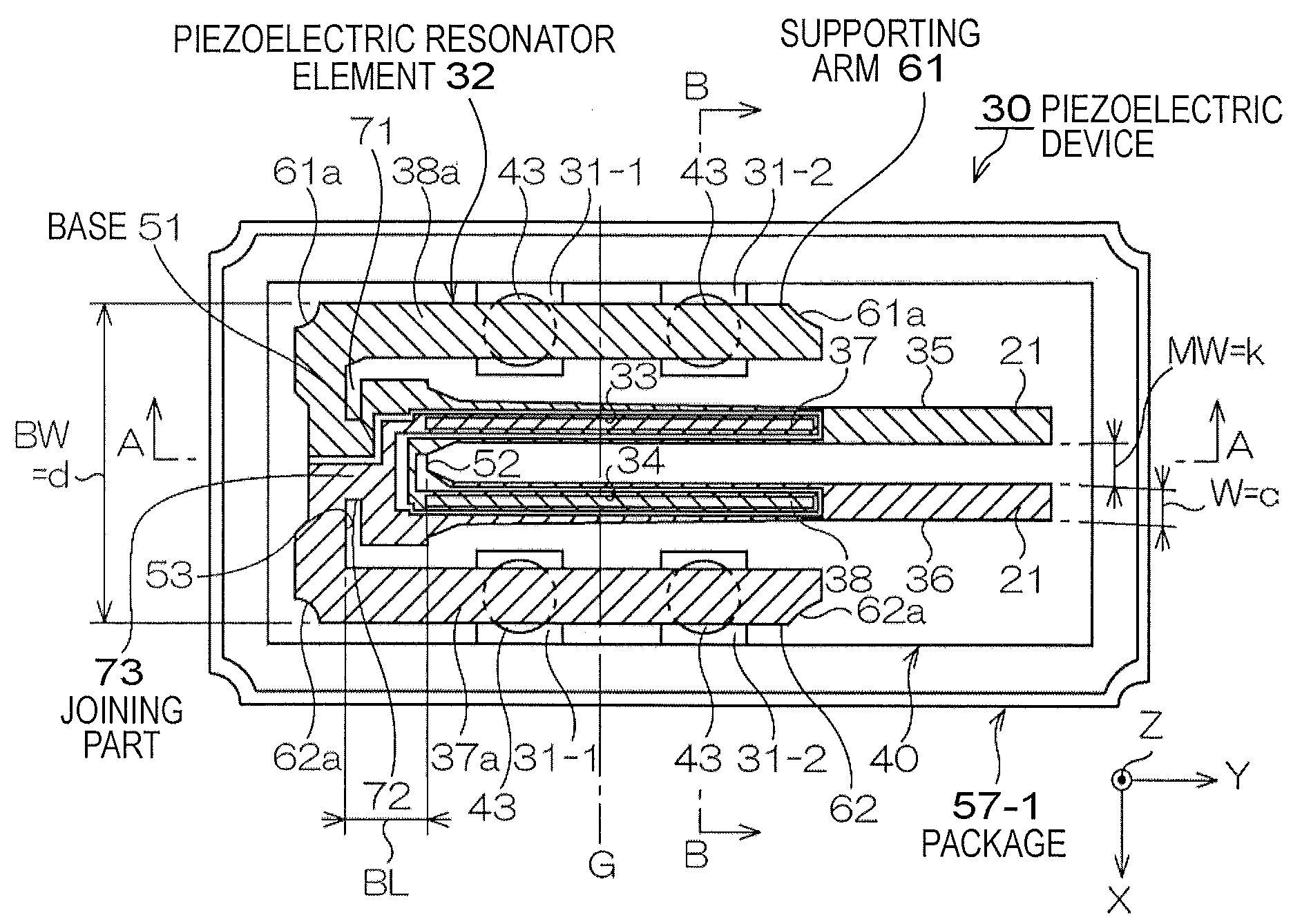
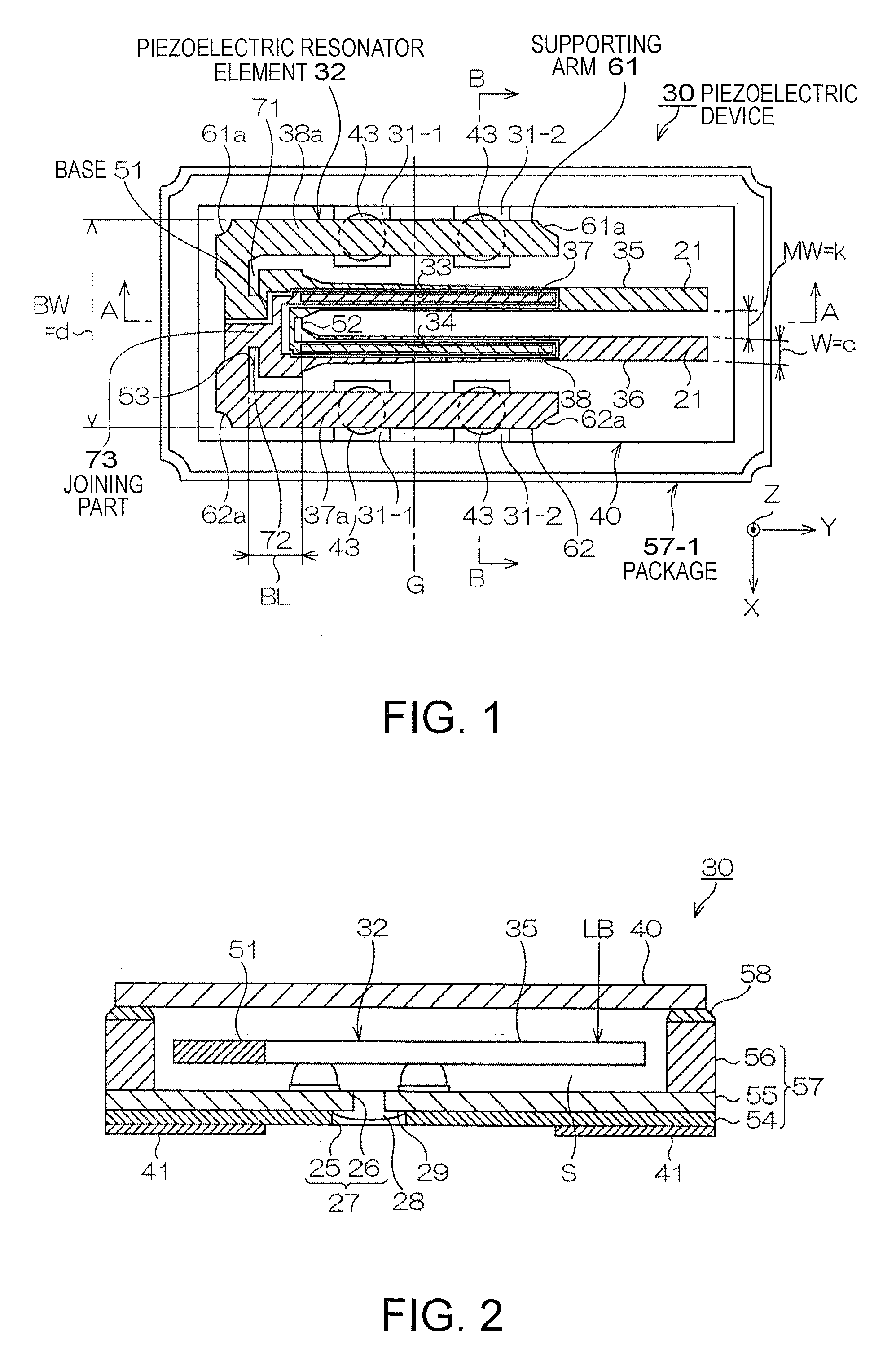
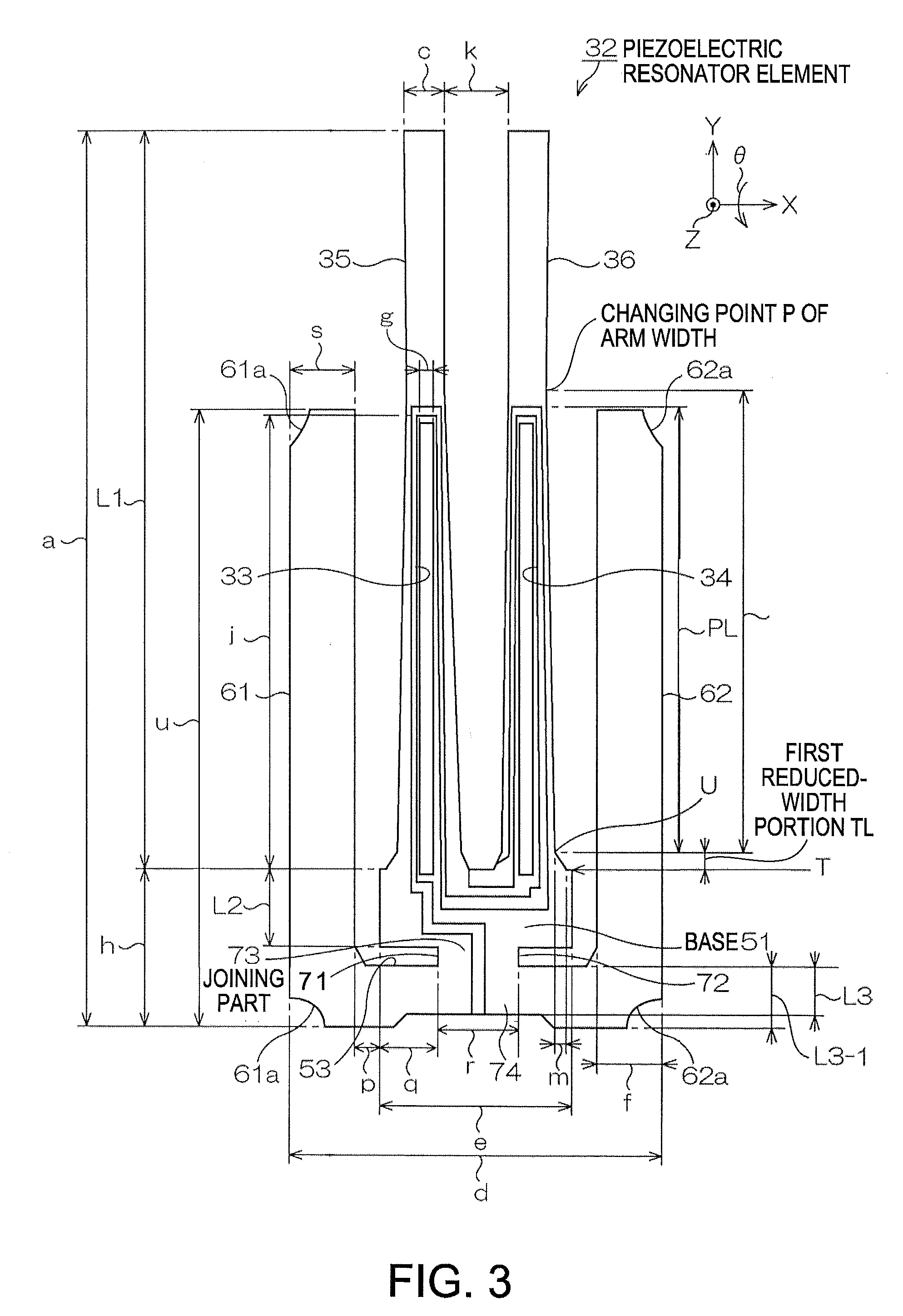
[0067]FIGS. 1 and 2 show a piezoelectric device according to an embodiment of the invention. FIG. 1 is a schematic plan view thereof, and FIG. 2 is a schematic sectional-view taken along a line A-A in FIG. 1. In addition, FIG. 3 is an enlarged plan view to explain details of a piezoelectric resonator element 32 in FIG. 1. FIG. 4 is a sectional view taken along a line B-B on resonating arms in FIG. 1.

[0068]Referring to the drawings, a piezoelectric device 30 is an example including a piezoelectric resonator. The piezoelectric device 30 houses the piezoelectric resonator element 32 in a package 57 serving as a base body.

[0069]As shown in FIGS. 1 and 2, the package 57 is formed in a rectangular box shape, for example, by laminating a first substrate 54, a second substrate 55, and a third substrate 56. For example, it is formed as follows: a ceramic green sheet made of aluminum oxide is formed as an insulation material; the sheet is formed in a shape as shown in the figures; and then fi...


PUM


Abstract

A piezoelectric resonator element includes: a base in a predetermined length, the base being made of a piezoelectric material; a plurality of resonating arms extending from a first end of the base; a joining part connected to a second end apart from the first end of the base by a predetermined distance; a connecting part connected to the joining part and extending in a width direction of the piezoelectric resonator element; a supporting arm connected to the connecting part and extending in a same direction as the resonating arm at an outer side of the plurality of resonating arms. A ratio L3/h is 40% or less where h is a length dimension from the first end of the base to the second end opposite to the resonating arms of the piezoelectric resonator element, and L3 is a width dimension of the connecting part connecting the supporting arm to the base through the joining part.

Description

BACKGROUND[0001]1. Technical Field[0002]The present invention relates to improvement on a piezoelectric resonator element and a piezoelectric device including the piezoelectric resonator element in its package or case.[0003]2. Related Art[0004]Piezoelectric devices, including a piezoelectric resonator, a piezoelectric oscillator and the like, have been widely used for small-sized information equipment, such as hard disc drives (HDDs), mobile computers, and IC cards, and for mobile communications equipment such as cellular phones, car-phones, and paging systems, and piezoelectric gyro sensors, etc.[0005]FIG. 14 is a schematic plan view illustrating an example of a piezoelectric resonator element conventionally used in the piezoelectric devices.[0006]In the figure, a piezoelectric resonator element 1, whose shape shown in the figure is formed by etching a piezoelectric material such as quartz or the like, is provided with a base 2 having a rectangular shape, which is mounted to a pack...

Claims


Application Information

Patent Timeline
Patent Type & Authority Applications(United States)
IPC IPC(8): H03H9/205H01L41/047H01L41/053
CPCH03H3/04H03H9/1021H03H2003/0492H03H2003/026H03H9/21
Inventor TANAYA, HIDEOYAMADA, YOSHIYUKITONEGAWA, YUKIHIROKURODA, KATSUMI
Owner TOYO TSUSHINKI
Why Eureka
Try Eureka