CPP-type magnetoresistive element having spacer layer that includes semiconductor layer

a magnetoresistive element and spacer layer technology, applied in the field of magnetoresistive elements and to thin film magnetic heads, can solve the problems of shortening the service life of tmr elements, deterioration of tmr elements, and degrading the high frequency response of read heads, and achieve stable characteristics and high mr ratio.

Inactive Publication Date: 2008-09-11
TDK CORPARATION
View PDF6 Cites 7 Cited by
  • Summary
  • Abstract
  • Description
  • Claims
  • Application Information

AI Technical Summary

Benefits of technology

[0023]It is an object of the present invention to provide a magnetoresistive element that utilizes a tunneling magnetoresistive effect and achieves a high MR ratio and stable characteristics...

Problems solved by technology

However, a TMR element with a high resistance would cause a high stray capacitance in the TMR element and a circuit connected thereto, thereby degrading the high frequency response of the read head.
However, an excessive reduction in the thickness of the tunnel barrier layer made of an insulating layer would cause a number of pinholes to develop in the tunnel barrier layer, resulting in a shorter service life of the TMR element.
In addition to this, a magnetic coupling may also be established between the free layer and the pinned layer, resulting in deterioration of characteristics of the TMR element such as an increase in noise and a reduction in MR ratio.
On the other hand, a CPP-GMR element has a problem that it cannot provide a sufficiently high MR ratio.
Additionally, a CPP-GMR element is small in magnetoresistance change amount because of its low resistance.
However, the application of a higher voltage to the element would raise the following problems.
As the volta...

Method used


Image

  • CPP-type magnetoresistive element having spacer layer that includes semiconductor layer
  • CPP-type magnetoresistive element having spacer layer that includes semiconductor layer
  • CPP-type magnetoresistive element having spacer layer that includes semiconductor layer

Examples


first embodiment

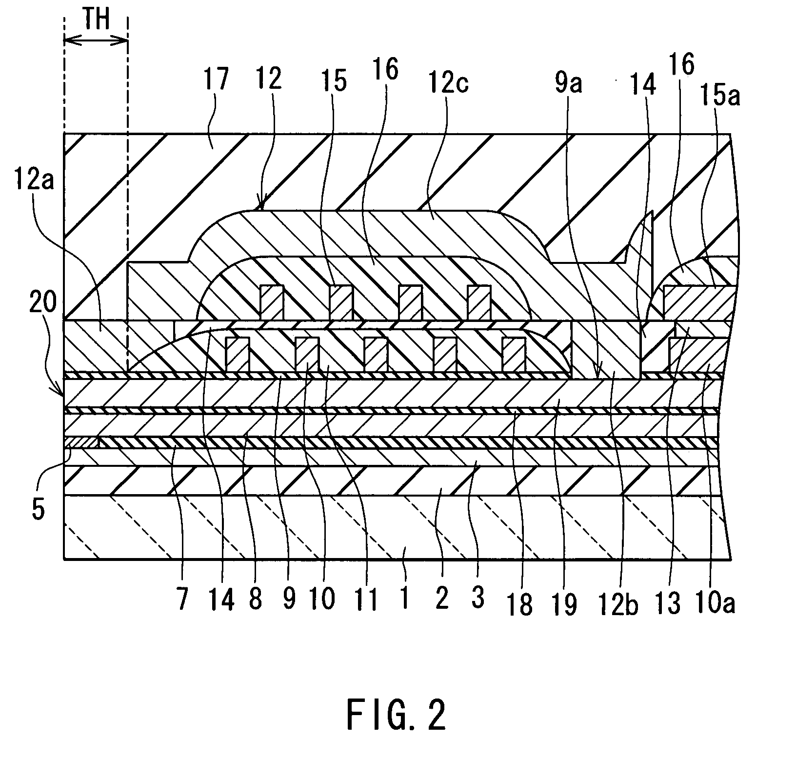
[0053]Embodiments of the present invention will now be described in detail with reference to the accompanying drawings. Reference is now made to FIG. 2 and FIG. 3 to describe the outlines of the configuration and a manufacturing method of a thin-film magnetic head of a first embodiment of the invention. FIG. 2 is a cross-sectional view illustrating a cross section of the thin-film magnetic head orthogonal to a medium facing surface and a substrate. FIG. 3 is a cross-sectional view illustrating a cross section of a pole portion of the thin-film magnetic head parallel to the medium facing surface.

[0054]The thin-film magnetic head of the first embodiment has a medium facing surface 20 that faces toward a recording medium. Furthermore, the thin-film magnetic head includes: a substrate 1 made of a ceramic material such as aluminum oxide and titanium carbide (Al2O3—TiC); an insulating layer 2 made of an insulating material such as alumina (Al2O3) and disposed on the substrate 1; a first s...

second embodiment

[0131]A magnetic memory element of a second embodiment of the invention will now be described with reference to FIG. 10 to FIG. 15. FIG. 10 to FIG. 15 are cross-sectional views respectively illustrating first to sixth examples of the magnetic memory element of the embodiment.

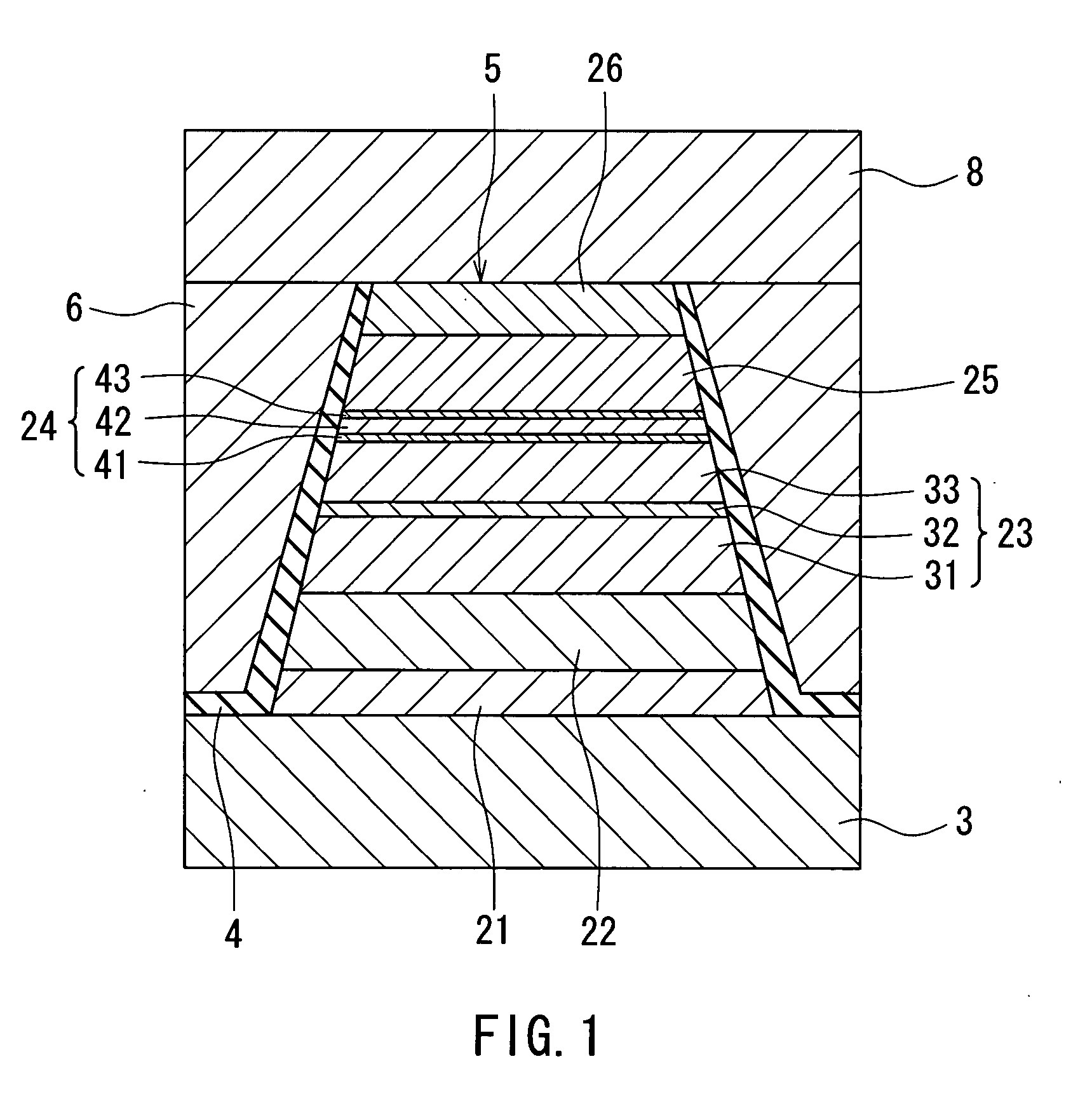
[0132]As shown in FIG. 10 to FIG. 15, the magnetic memory element 50 of the second embodiment has a basic configuration the same as that of the MR element 5 of the first embodiment. Specifically, the magnetic memory element 50 includes: a free layer 25 that is a ferromagnetic layer whose direction of magnetization changes; a pinned layer 23 that is a ferromagnetic layer whose direction of magnetization is fixed; and a spacer layer 24 disposed between the free layer 25 and the pinned layer 23. The magnetic memory element 50 further includes: an antiferromagnetic layer 22 disposed on a side of the pinned layer 23 farther from the spacer layer 24; an underlying layer 21 disposed on a side of the antiferromagnetic l...


PUM


Abstract

An MR element includes: a free layer whose direction of magnetization changes in response to a signal magnetic field; a pinned layer whose direction of magnetization is fixed; and a spacer layer disposed between these layers. The spacer layer includes: a semiconductor layer made of an n-type semiconductor; and a Schottky barrier forming layer made of a metal material having a work function higher than that of the n-type semiconductor that the semiconductor layer is made of, the Schottky barrier forming layer being disposed in at least one of a position between the semiconductor layer and the free layer and a position between the semiconductor layer and the pinned layer, touching the semiconductor layer and forming a Schottky barrier at an interface between the semiconductor layer and itself The semiconductor layer is 1.1 to 1.7 nm in thickness, and the Schottky barrier forming layer is 0.1 to 0.3 nm in thickness.

Description

BACKGROUND OF THE INVENTION[0001]1. Field of the Invention[0002]The present invention relates to a magnetoresistive element, and to a thin-film magnetic head, a head gimbal assembly, a head arm assembly and a magnetic disk drive each of which includes the magnetoresistive element, and relates to a magnetic memory element.[0003]2. Description of the Related Art[0004]Performance improvements in thin-film magnetic heads have been sought as areal recording density of magnetic disk drives has increased. A widely used type of thin-film magnetic head is a composite thin-film magnetic head that has a structure in which a write head having an induction-type electromagnetic transducer for writing and a read head having a magnetoresistive element (that may be hereinafter referred to as MR element) for reading are stacked on a substrate.[0005]MR elements include GMR (giant magnetoresistive) elements utilizing a giant magnetoresistive effect, and TMR (tunneling magnetoresistive) elements utilizi...

Claims


Application Information

Patent Timeline
IPC IPC(8): G11B5/39
CPCB82Y10/00G11B2005/3996G11B5/3906B82Y25/00
Inventor HIRATA, KEIMIURA, SATOSHIKAGAMI, TAKEOSASAKI, TETSURO
Owner TDK CORPARATION
Why Eureka
Try Eureka