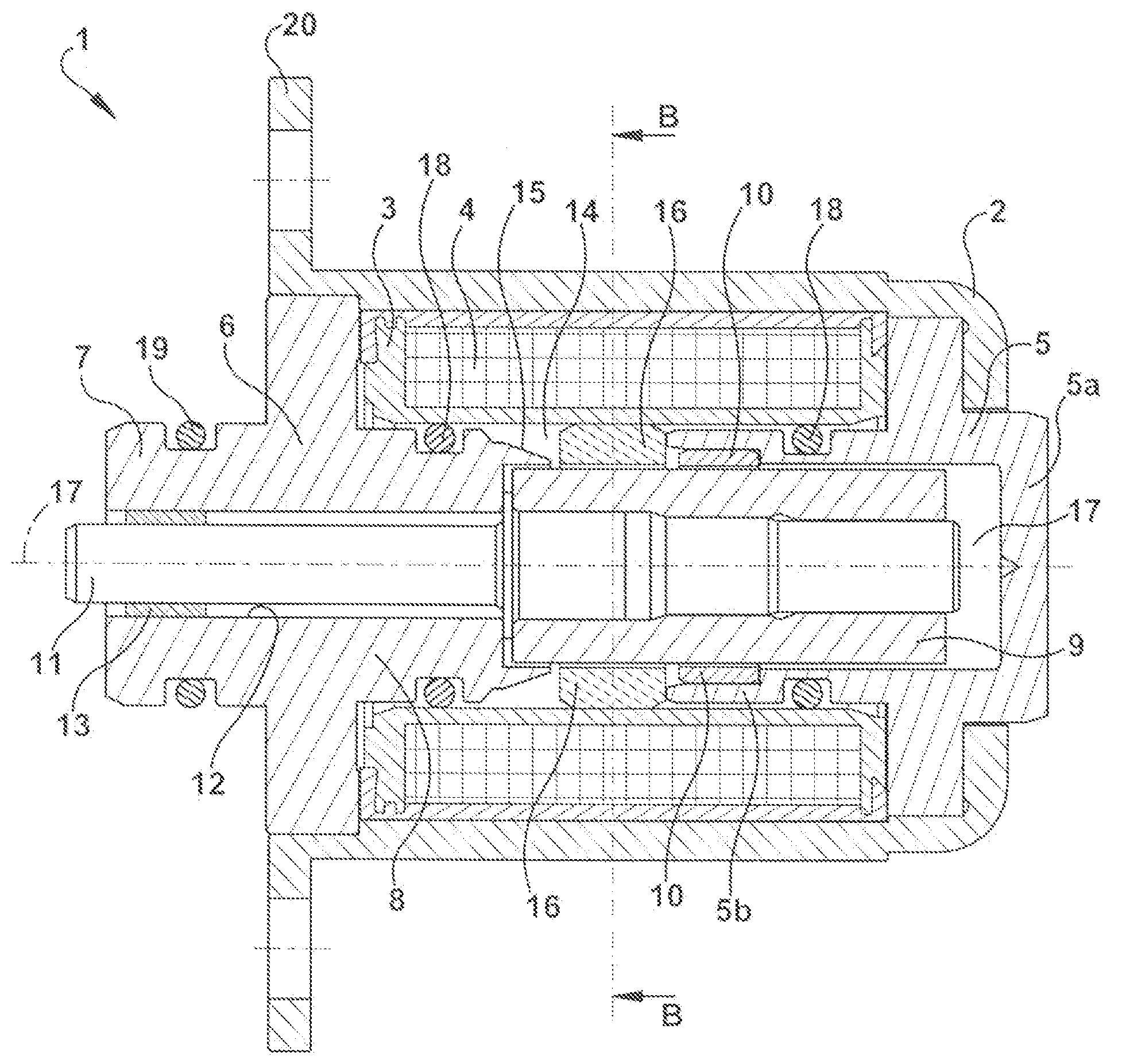
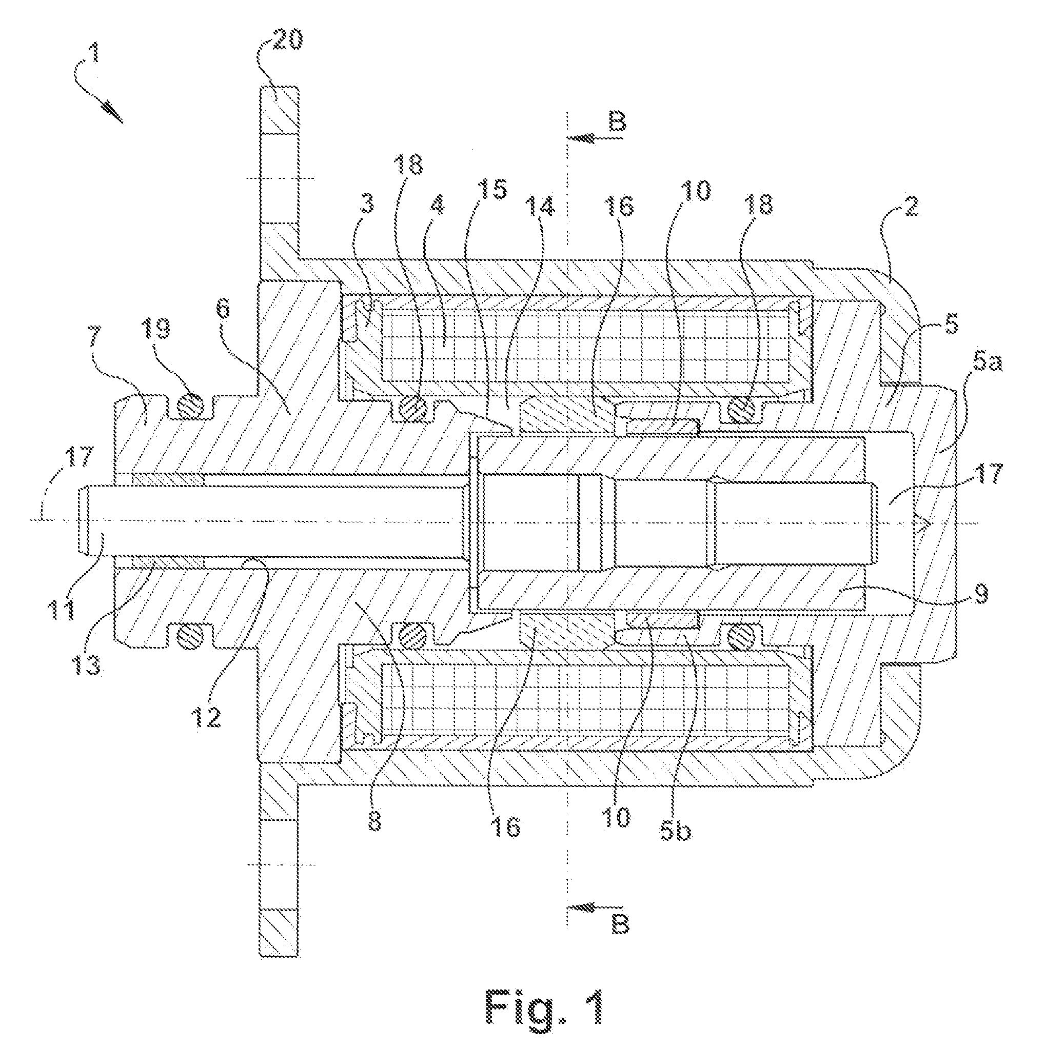
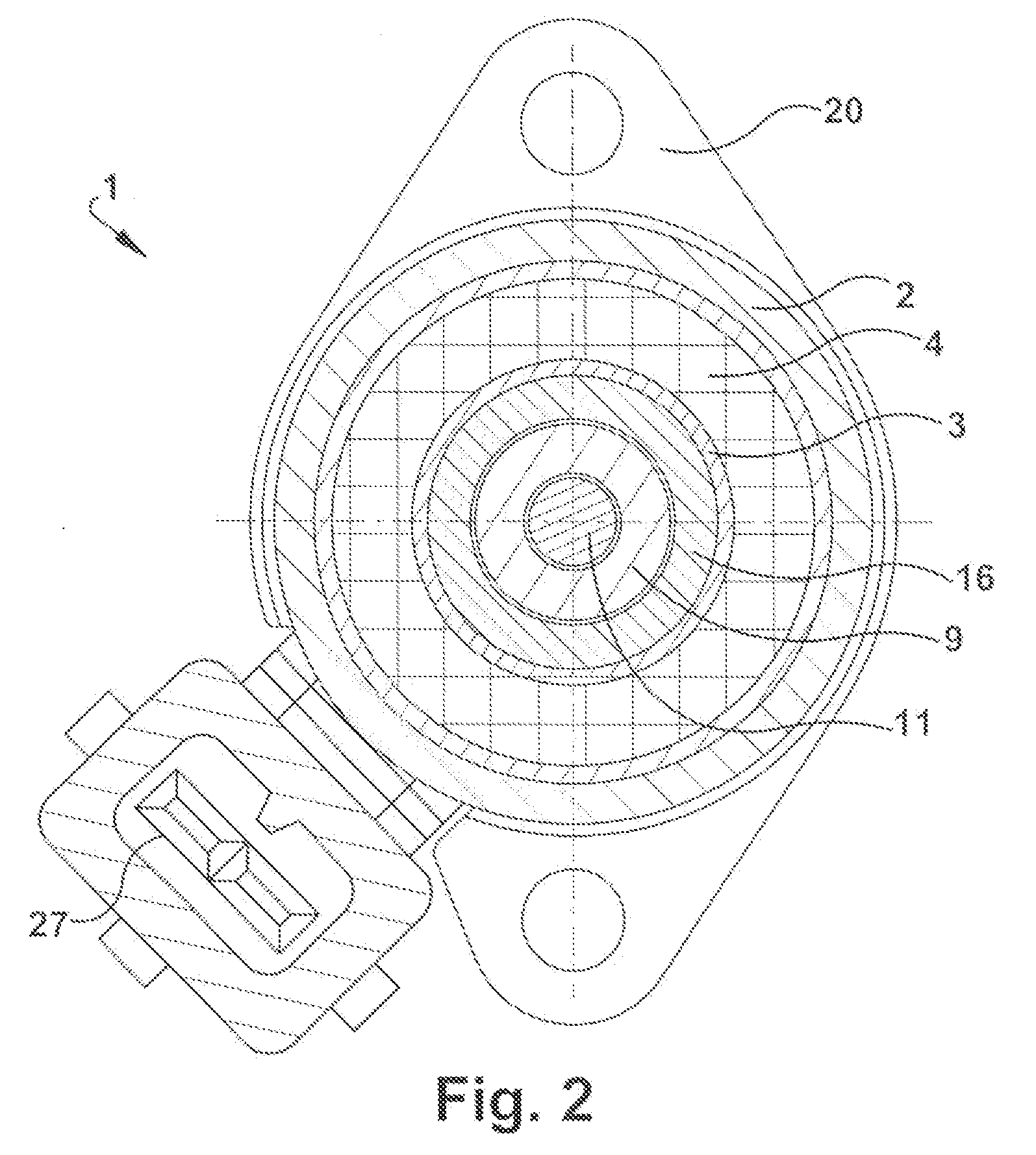
[0015]In one embodiment, the arrangement of the electrically conductive element within the gap is related to two geometrical features of the element. Firstly, a length of the element axially and substantially parallel to the longitudinal axis of the coil body is small because said length is restricted by the adjoining axial end faces of the pole shoes. Furthermore, the radial distance of the element with respect to a center axis of the coil body or of the magnet armature arranged in a displaceable manner on said center axis is small. These geometrical features of the electrically conductive element result in two advantageous effects with regard to the
magnetic field: The small length of the element leads to a relatively greater curvature of the field lines of the
magnetic field induced by said element. This means that the field lines of the
magnetic field form an angle with the longitudinal axis of the coil body, but do not run parallel thereto. As a result of this, comparatively large radial force components act on the magnet armature in the direction of the center axis of the coil body if the magnet armature moves radially with respect to the winding. Furthermore, the comparatively small radial distance of the element with respect to the center axis of the coil body or with respect to the magnet armature has the effect that the change in the
magnetic flux density assumes a relatively high magnitude if the magnet armature moves radially with respect to the winding. The change in the
magnetic flux density with respect to the element enclosing the magnetic armature is different from zero in the case of a radial movement of the element relative to the winding, such that a current is induced in the element. Said current in turn generates in the element a magnetic field that acts on the magnet armature in the manner of a funnel. To put it another way, the magnetic field generated in the element brings about a funnel effect which forces the magnet armature back in the direction of the center axis of the coil body or back to said axis. In the case of a radial movement of the magnet armature, therefore, the magnetic field generated in the element precisely by said radial movement of the magnet armature gives rise to a self-stabilizing effect with respect to the center axis of the coil body for the magnet armature in the manner of the funnel effect explained.
[0016]The proportional magnet according to one embodiment of the invention further provides the
advantage that the element as such does not have to be produced from a metallic material, but rather solely the electrically conductive layer which is applied separately on the basic body, forms a conductor track enclosing the magnet armature. Consequently, the production of the basic body can be achieved with more flexibility with regard to the manufacturing of said basic body and the corresponding
material selection. By way of example, the basic body can be produced inexpensively from a plastic by means of injection molding.
[0017]In one advantageous embodiment of the invention, the element, if it is made of a metallic material, and the electrically conductive layer, respectively, can have a
metallic coating that provides protection against
corrosion. Such a
coating can, in one example, be produced by chemical
tin-plating or else electrolytic gold-plating. The
coating therefore prevents an undesirable
corrosion of the element and of the conductive layer, respectively, and therefore ensures a high functional reliability of the proportional magnet in conjunction with a long lifetime.
[0018]The above-explained small height of the element with respect to a longitudinal axis of the coil body can be obtained by the element being formed as a ring. The ring encloses the magnet armature in every position thereof with respect to the coil body or the winding. This ensures the advantageous curvature of the field lines of the magnetic field generated in the ring with respect to the longitudinal axis of the coil body.
[0019]In an advantageous embodiment of the invention, an internal
diameter of the ring can be at most as small as the external
diameter of the magnet armature, a displaceability of the magnet armature through the ring being ensured. In this case, the ring is brought with its internal circumferential area very close to an external circumference of the magnet armature without these components getting stuck together. Furthermore, an external
diameter of the ring can be chosen to be at most as large as an external diameter of at least one of the two pole shoes. This has the effect firstly that the ring is still arranged within the air gap axially between the two pole shoes, and furthermore the length of the ring is maximal in this arrangement. Consequently, the
eddy current generated in the ring during a radial movement of the magnet armature assumes a high magnitude, wherein a magnetic field generated by said
eddy current damps the radial movement of the magnet armature and forces the latter back to the center axis of the proportional magnet or of the coil body. This has already been explained above as the funnel effect.
[0020]In an advantageous embodiment of the invention, the element or the ring can be produced from a metallic material, for example from
copper or aluminum. This ensures a sufficiently
high magnetic field which is generated in the element or the ring on account of the current induced therein.


