Clathrate compounds and method of manufacturing
a technology of clathrate compounds and manufacturing methods, applied in the direction of vehicle route interaction devices, railway components, nuclear engineering, etc., can solve the problems of many technologies limited by the materials they use, and achieve the effect of easy integration into current electronics technologies and high efficiency
- Summary
- Abstract
- Description
- Claims
- Application Information
AI Technical Summary
Benefits of technology
Problems solved by technology
Method used
Image
Examples
first embodiment
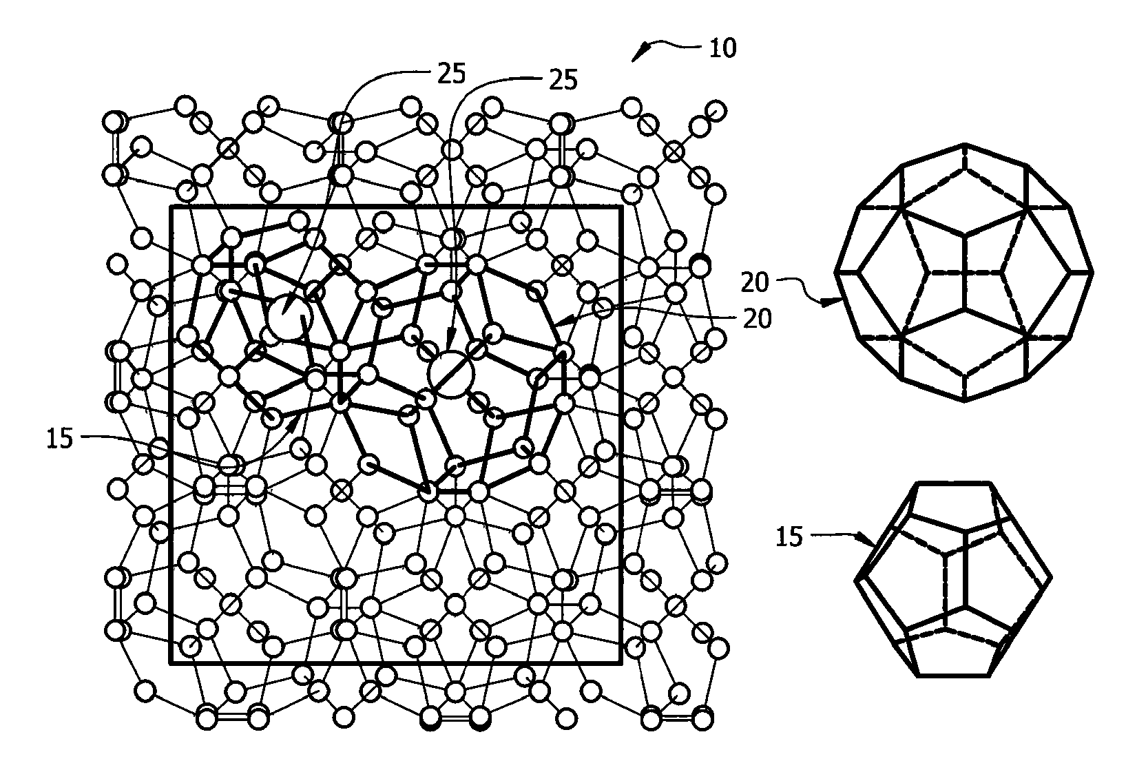
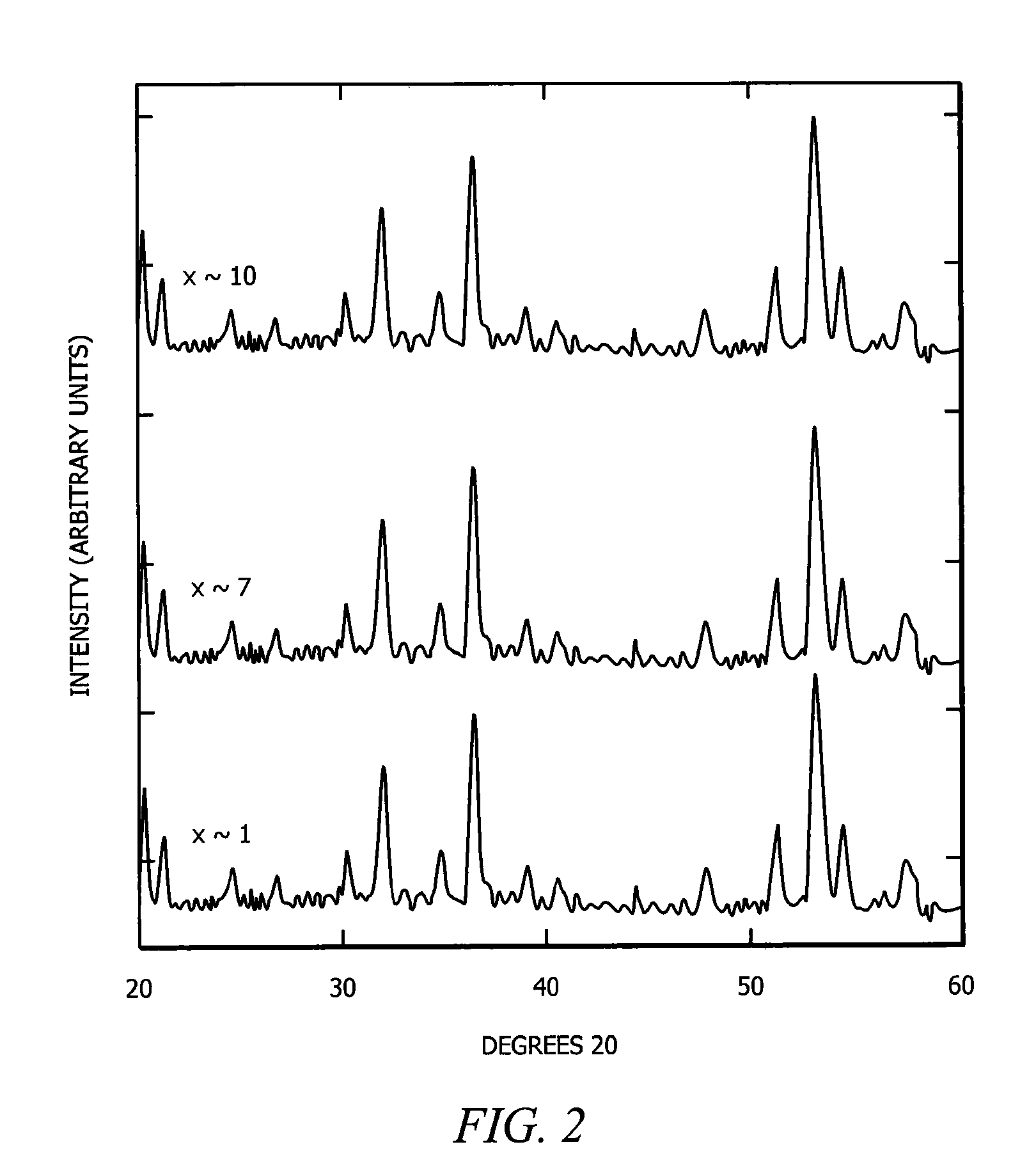
[0024]In a first embodiment, intermediate Zintl compounds are used. Some examples include, but are not limited to NaSi, NaGe, NaSn, KSi, KGe, KSn, RbxSi, RbGe, RbSn, CsSi, CsGe, CsSn, BaSi2, BaGe2, BaSn2, SrSi2, SrGe2, SrSn2, Na1-xKxSi2, Na1-xKxGe2, Na1-xKxSn2, Na1-xRbxSi2, Na1-xRbxGe2, Na1-xRbxSn2, Na1-xCsxSi2, Na1-xCsxGe2, Na1-xCsxSn2, K1-xRbxSi2, K1-xRbxGe2, K1-xRbxSn2, K1-xCsxSi2, K1-xCsxGe2, K1-xCsxSn2, Rb1-xCsxSi2, Rb1-xCsxGe2, Rb1-xCsxSn2, NaSi1-yGey, KSi1-yGey, RbSi1-yGey, CsSi1-yGey, Na1-xKxSi1-yGey, Na1-xRbxSi1-yGey, Na1-xCsxSi1-yGey, K1-xRbxSi1-yGey, K1-xCsxSi1-yGey, and Rb1-xCsxSi1-yGey (0xSi136. The guest atom content is controlled by the amount of time the material is heated in the furnace. For example, a NaxSi136 material heated for eight hours at 420° C. results in x=8, while a NaxSi136 material heated for twenty-four hours at 420° C. results in x=1.
second embodiment
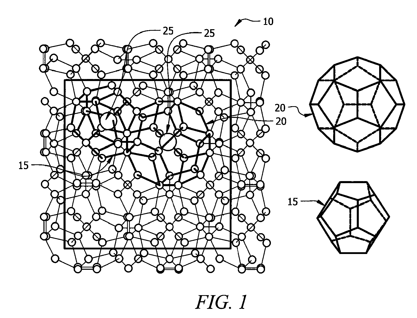
[0025]In a second embodiment, stoichiometric amounts of high purity elements are combined in a tungsten or tantalum crucible sealed in a steel canister under nitrogen gas at a pressure of one atmosphere. The steel canister is itself sealed under nitrogen in a quartz tube. The mixture is reacted at 800° C. for 48 hours, then cooled to 650° C. and held at this temperature for seven days. The compound is then cooled to room temperature. This produces high purity type II clathrates with general compositions of A24E136-yMy, A8B16E136-yMy, A8B16Si136-yGey and A8B16Si136-y-zGeyMz, where A and B include, but are not limited to Na, K, Cs, Rb, Ca, Ba, Sr, Eu, M includes, but is not limited to Ni, Pd, Pt, Cu, Ag, Au, Zn, Al, Ga, In, P, As, and Sb, and E is Si, Ge, or Sn.
third embodiment
[0026]In a third embodiment, the guest atom content in type II clathrates of general composition A24E136-yMy, A8B16E136-yMy, A8B16Si136-yGey and A8B16Si136-y-zGeyMz is varied, resulting in the general compositions AxE136-yMy, AxBmE136-yMy, AxSi136-yGey AxBmSi136-yGey and AxBmSi136-y-zGeyMz. Type II clathrates of the composition A24E136-yMy, A8B16E136-yMy, A8B16Si136-yGey and A8B16Si136-yGeyMz are first synthesized using the method outlined in the previous paragraph. These are referred to as “fully occupied” or “stoichiometic,” in as much as all of the polyhedra are occupied by guest atoms. These compounds are then ground to fine powders and annealed at temperatures between 300° C. and 500° C. under high vacuum of 10−5 to 10−6 torr. The process of grinding and annealing is repeated as necessary, and the temperature is increased each time as necessary. This vacuum annealing or “degassing” removes a portion of the guest atoms from the polyhedra, leaving these polyhedra unoccupied. Thus...
PUM
| Property | Measurement | Unit |
|---|---|---|
| Temperature | aaaaa | aaaaa |
| Temperature | aaaaa | aaaaa |
| Temperature | aaaaa | aaaaa |
Abstract
Description
Claims
Application Information
 - R&D
- Intellectual Property
- Life Sciences
- Materials
- Tech Scout
- Unparalleled Data Quality
- Higher Quality Content
- 60% Fewer Hallucinations
Browse by: Latest US Patents, China's latest patents, Technical Efficacy Thesaurus, Application Domain, Technology Topic, Popular Technical Reports.
© 2025 PatSnap. All rights reserved.Legal|Privacy policy|Modern Slavery Act Transparency Statement|Sitemap|About US| Contact US: help@patsnap.com


