
Toner for developing latent electrostatic image, two-component developer, image forming method and image forming apparatus

Inactive Publication Date: 2008-09-25
RICOH KK
View PDF26 Cites 38 Cited by
  • Summary
  • Abstract
  • Description
  • Claims
  • Application Information

AI Technical Summary

Benefits of technology

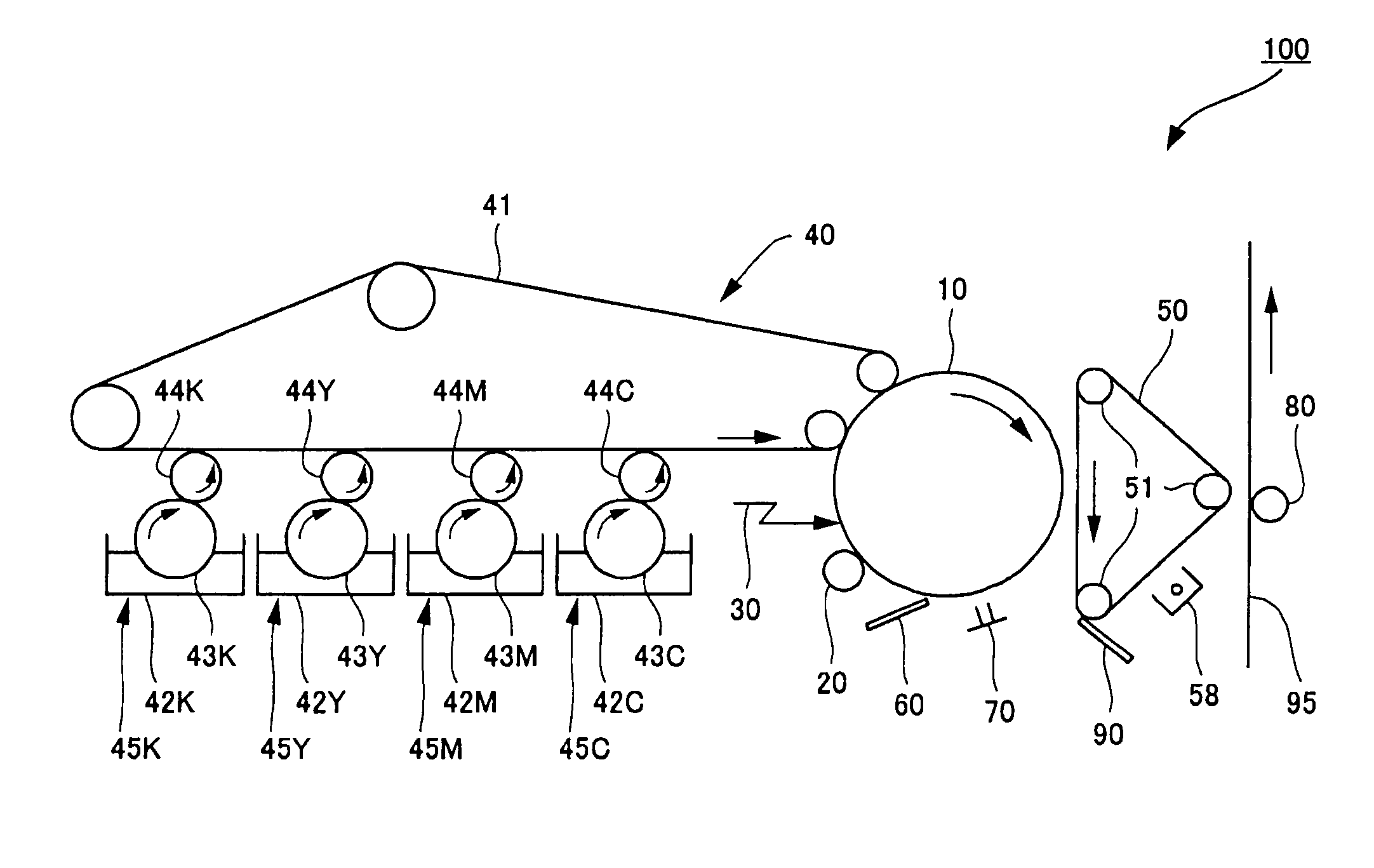
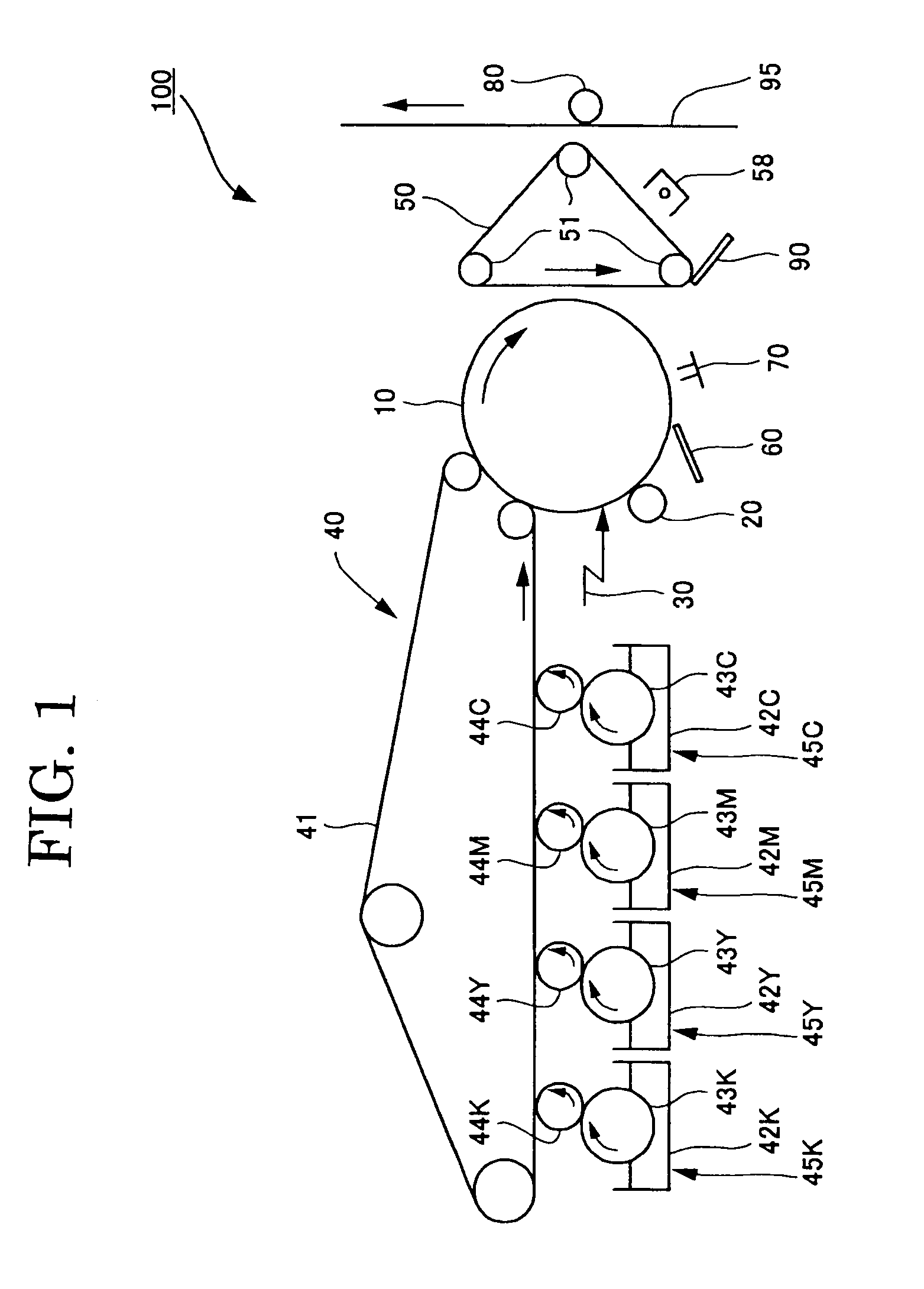
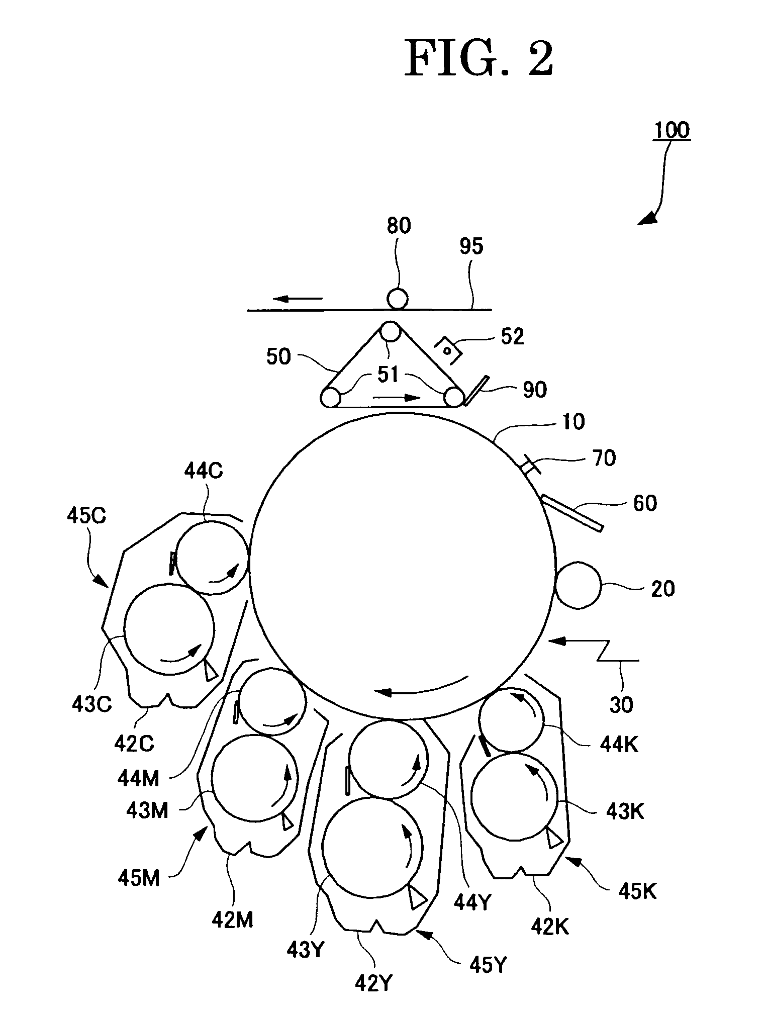
[0010]The present invention is designed in light of the problems in related art and aimed at providing a toner which, despite its spherical shape, makes it possible to prevent an external additive from being embedded in the toner easily or by a load generating low stress, reduce variation in image density, maintain cleaning ability and transfer ability throughout its long-term use and obtain excellent image quality, and further, providing a two-component developer, an image forming method and an image forming apparatus with the use of the toner.

Problems solved by technology

However, from the point of view of users who are familiar with printed materials, images produced by full-color copiers are still not satisfactory, and further improvement in image quality is demanded to achieve the high definition and high resolution of photographs and printed materials.
The pulverization method is known to be capable of producing toners with fairly superior properties; however, selection of materials for the toners is limited.
This demand requires compositions obtained through melting and mixing to be sufficiently brittle.
For this reason, when the compositions are actually pulverized into particles, it is likely that a wide particle size distribution is created, and if an attempt is made to obtain copied images having excellent resolution and gray-scale properties, it is necessary to remove fine powders that are 5 μm or less in particle diameter and coarse particles that are 20 μm or greater in particle diameter through classification; hence, the pulverization method is disadvantageous in that the yield is very low.
Also in the pulverization method, it is difficult for the colorant, the charge control agent and the like to be evenly dispersed in the thermoplastic resin.
Uneven dispersion of additives has negative effects on the fluidity, image-developing properties and durability of the toners, image quality and the like.
However, there is a new problem created in which the presence state of external additives such as a fluidity-adding agent typified by silica is liable to change on surfaces of particles.
However, this invention cannot sufficiently prevent external additives from being embedded because the minimum fixing temperature rises, the low-temperature fixing properties, in other words the energy-saving image-fixing properties, are not sufficient, and the high-molecular-weight resin is a component of the toner particles, so that there is no significant change in the shape of particles.

Method used


Image

  • Toner for developing latent electrostatic image, two-component developer, image forming method and image forming apparatus
  • Toner for developing latent electrostatic image, two-component developer, image forming method and image forming apparatus
  • Toner for developing latent electrostatic image, two-component developer, image forming method and image forming apparatus

Examples


production example 1

—Synthesis of Fine Organic Particle Emulsion

[0201]In a reaction container equipped with a stirrer and a thermometer, 683 parts of water, 11 parts of sodium salt of ethylene oxide methacrylate adduct sulfate (ELEMINOL RS-30 produced by Sanyo Chemical Industries, Ltd.), 166 parts of methacrylic acid, 110 parts of butyl acrylate and 1 part of ammonium persulfate were placed, then these ingredients were stirred at 3,800 rpm for 30 min to give a white emulsion. The white emulsion was heated until the temperature in the system became 75° C., and was subjected to reaction for 4hr. Further, the white emulsion was provided with 30 parts of 1% ammonium persulfate solution and ripened at 75° C. for 6 hr to yield an aqueous dispersion solution [fine particle dispersion solution 1] of a vinyl resin (copolymer of methacrylic acid, butyl acrylate and sodium salt of ethylene oxide methacrylate adduct sulfate). The volume average particle diameter of [fine particle dispersion solution 1] measured b...

production examples 2 to 5

[0219]Particles 2 to 5 having protruding portions on surfaces of toner base particles were obtained in a manner similar to the particles 1 in Production Example 1, except that the protrusion-forming fine resin particles A added into the aqueous phase in production Example 1 were changed as shown in Table 1.

production example 6

[0220]Toner base particles 6 were obtained in a manner similar to the particles 1 in Production Example 1, except that the protrusion-forming fine resin particles A added into the aqueous phase in production Example 1 were not used.

(Production of Carrier)

[0221]

Core materialMn ferrite particles (weight average diameter: 35 μm)5,000partsCoating materialstoluene200partssilicone resin SR2400 (produced by Dow Corning200partsToray Co., Ltd., nonvolatile content: 50%)AMINOSILANE SH6020 (produced by Dow Corning7partsToray Co., Ltd.)carbon black4parts

[0222]A coating solution was prepared by dispersing the above-mentioned coating materials for 10 min using a stirrer. This coating solution and the core material were poured into a coating apparatus in which a rotary bottom plate disk and an stirring blade were provided in a fluidized bed and coating was performed by forming a swirling flow, and the coating solution was thus applied onto the core material. The applied product was embedded in an ...


PUM

PropertyMeasurementUnit
Particle diameteraaaaaaaaaa
Diameteraaaaaaaaaa

Abstract

The present invention provides a toner which, despite its spherical shape, makes it possible to prevent an external additive from being embedded in the toner easily or by a load generating low stress, reduce variation in image density, maintain cleaning ability and transfer ability throughout its long-term use and obtain excellent image quality, and further, provides a two-component developer, an image forming method and an image forming apparatus with the use of the toner. There is a toner including: base particles including a colorant and a resin, and hard fine particles, wherein the base particles and the hard fine particles are mixed together, and protruding portions formed of fine organic resin particles which are different in composition from a resin contained as a main component in the base particles are provided on surfaces of the base particles.

Description

BACKGROUND OF THE INVENTION[0001]1. Field of the Invention[0002]The present invention relates to a toner for developing latent electrostatic images and to a two-component developer, an image forming method and an image forming apparatus that use the same.[0003]2. Description of the Related Art[0004]In an electrophotographic apparatus or electrostatic recording apparatus, a toner is attached to a latent electrostatic image formed on a photoconductor, the toner-attached image is transferred onto a transfer material, then the toner is thermally fixed onto the transfer material to yield a toner image. In full-color image formation, in general, colors are reproduced using toners of four colors, i.e. black, yellow, magenta and cyan, and a full-color image is obtained by developing each color, simultaneously heating toner layers deposited on top of one another over a transfer material and fixing the toner layers. However, from the point of view of users who are familiar with printed materi...

Claims


Application Information

Patent Timeline
IPC IPC(8): G03G13/14G03G9/083G03G15/01
CPCG03G9/0806G03G9/0819G03G9/0825G03G9/0827G03G9/08711G03G2215/0607G03G9/08795G03G9/08797G03G13/16G03G2215/0119G03G9/08793
Inventor KOTSUGAI, AKIHIROYAMASHITA, HIROSHI
Owner RICOH KK
Learn More