
Interspinous dynamic stabilization implant and method of implanting

a dynamic stabilization and implanting technology, applied in the field of interspinous dynamic stabilization implant and method of implanting, can solve the problems of inability to fully absorb the blood, substantial infection risk, profuse bleeding, etc., and achieve the effect of superior spinous process and convenient relative tilting and rotation movemen

Inactive Publication Date: 2008-09-25
WANG JEFFREY CHUN +3
View PDF10 Cites 137 Cited by
  • Summary
  • Abstract
  • Description
  • Claims
  • Application Information

AI Technical Summary

Benefits of technology

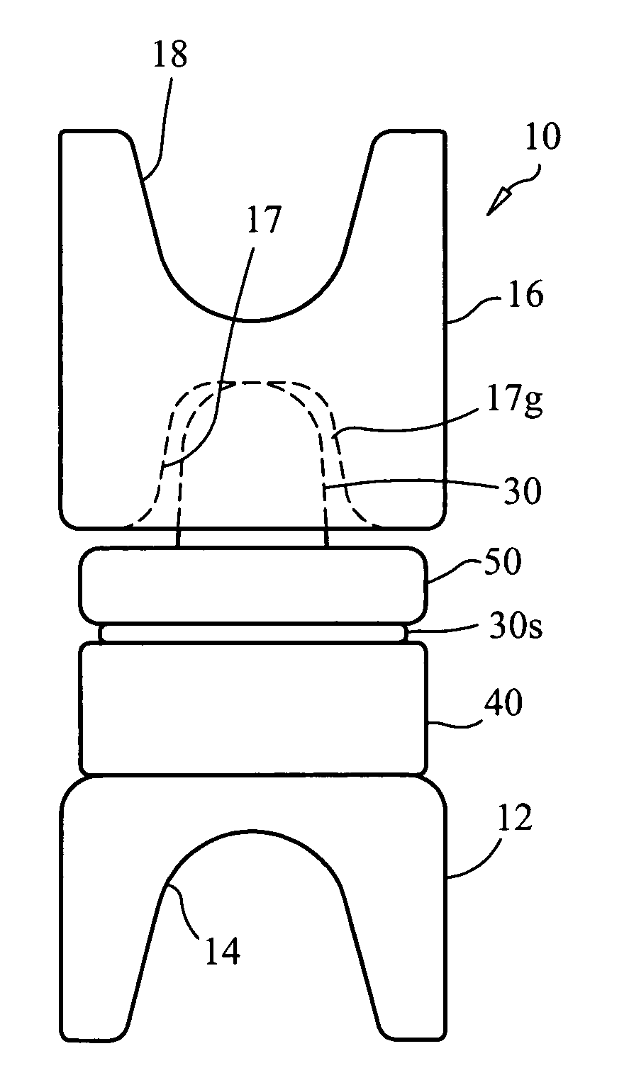
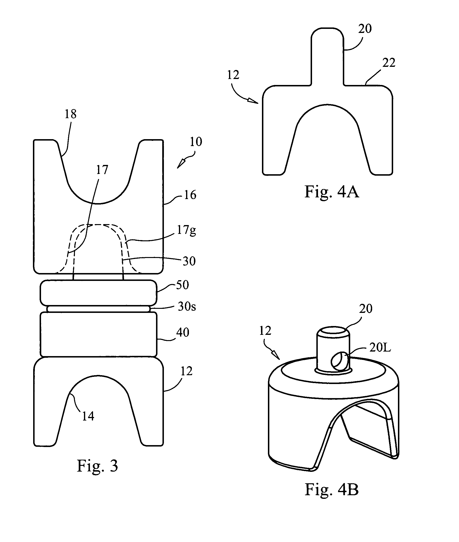
[0018]An interspinous implant device for distracting an adjacent pair of spinous processes while permitting relative flexion, lateral bending and side rotation motions between the vertebrae joined to the adjacent pair of spinous processes is provided, including: an inferior mount body configured to mate with a relatively inferior spinous process of the pair; a superior mount body configured to mate with a relatively superior spinous process of the pair; and a joint intermediate of the inferior mount body and the superior mount body; wherein upon implantation of the device between the spinous processes to contact the spinous processes, the joint facilitates relative tilting and rotation movements between the superior mount body and the inferior mount body.

Problems solved by technology

Many potentially negative side effects are inherent in this form of treatment, including profuse bleeding, substantial risk of infection, potential nerve damage sometimes leading to paralysis and / or bladder / bowel dysfunction, dural tears, persistent fluid leakage, arachnoiditis, continuing chronic pain, non-union (if fusion is performed), fusion hardware failure, donor site pain, adjacent segment disease, long operation times, and substantial operation costs.
There are inherent general risks of the surgical procedure and medical risks including, but not limited to: bleeding, infection, nerve or vessel damage, risks of anesthesia, death, need for further surgery, iatrogenic instability, epidural hematoma, failure or implants and / or associated hardware, misplacement of implants and hardware, migration of implants and hardware, heart attack, stroke, deep venous thrombosis, pulmonary embolism, spinal cord and nerve damage, reflex sympathetic dystrophy, sexual dysfunction, positioning problems, brachial plexus injuries, traction injuries, swallowing difficulties, problems with vocal cords, airway obstruction, postoperative swelling, need for prolonged intubation, persistent dural fistula, paralysis, blindness, no relief of current symptoms, possible development of new symptoms, possible worsening of current symptoms, possible need for intraoperative change of procedure, possible need for fusion of the spine as determined intraoperatively, and other rare risks not named above.
The need for fusion of the spine can be sometimes first recognized intraoperatively, when a spinal fusion was not originally planned to be performed, but when instability or iatrogenic instability is encountered during the procedure that would make the spine unstable if the fusion were not performed.
Further, many of these devices are rigid, inflexible and non-adjustable wedge-like implants that require dissection of muscle tissue and / or ligaments such as the supraspinous ligament and interspinous ligament.

Method used


Image

  • Interspinous dynamic stabilization implant and method of implanting
  • Interspinous dynamic stabilization implant and method of implanting
  • Interspinous dynamic stabilization implant and method of implanting

Examples


Embodiment Construction

[0051]Before the present devices and procedures are described, it is to be understood that this invention is not limited to particular embodiments described, as such may, of course, vary. It is also to be understood that the terminology used herein is for the purpose of describing particular embodiments only, and is not intended to be limiting, since the scope of the present invention will be limited only by the appended claims.

[0052]Where a range of values is provided, it is understood that each intervening value, to the tenth of the unit of the lower limit unless the context clearly dictates otherwise, between the upper and lower limits of that range is also specifically disclosed. Each smaller range between any stated value or intervening value in a stated range and any other stated or intervening value in that stated range is encompassed within the invention. The upper and lower limits of these smaller ranges may independently be included or excluded in the range, and each range...


PUM


Abstract

Devices and methods for treating spinal disorders and associated discomfort therefrom. In one embodiment, an interspinous implant device is configured for distracting an adjacent pair of spinous processes while permitting relative flexion, lateral bending and side rotation motions between the vertebrae joined to the adjacent pair of spinous processes. A method of treating spinal disorders and associated discomfort therefrom, includes inserting an interspinous device between a pair of adjacent spinous processes such that a superior portion of the device contacts an inferior surface of the relatively superior spinous process of the pair, and an inferior portion of the of the device contacts a superior surface of the relatively inferior spinous process of the pair; and distracting the superior and inferior portions, relative to one another, thereby distracting the spinous processes, whereby vertebrae integral with the spinous processes retain capability of flexion, lateral bending and side rotation motions, relative to one another, after the distraction has been performed.

Description

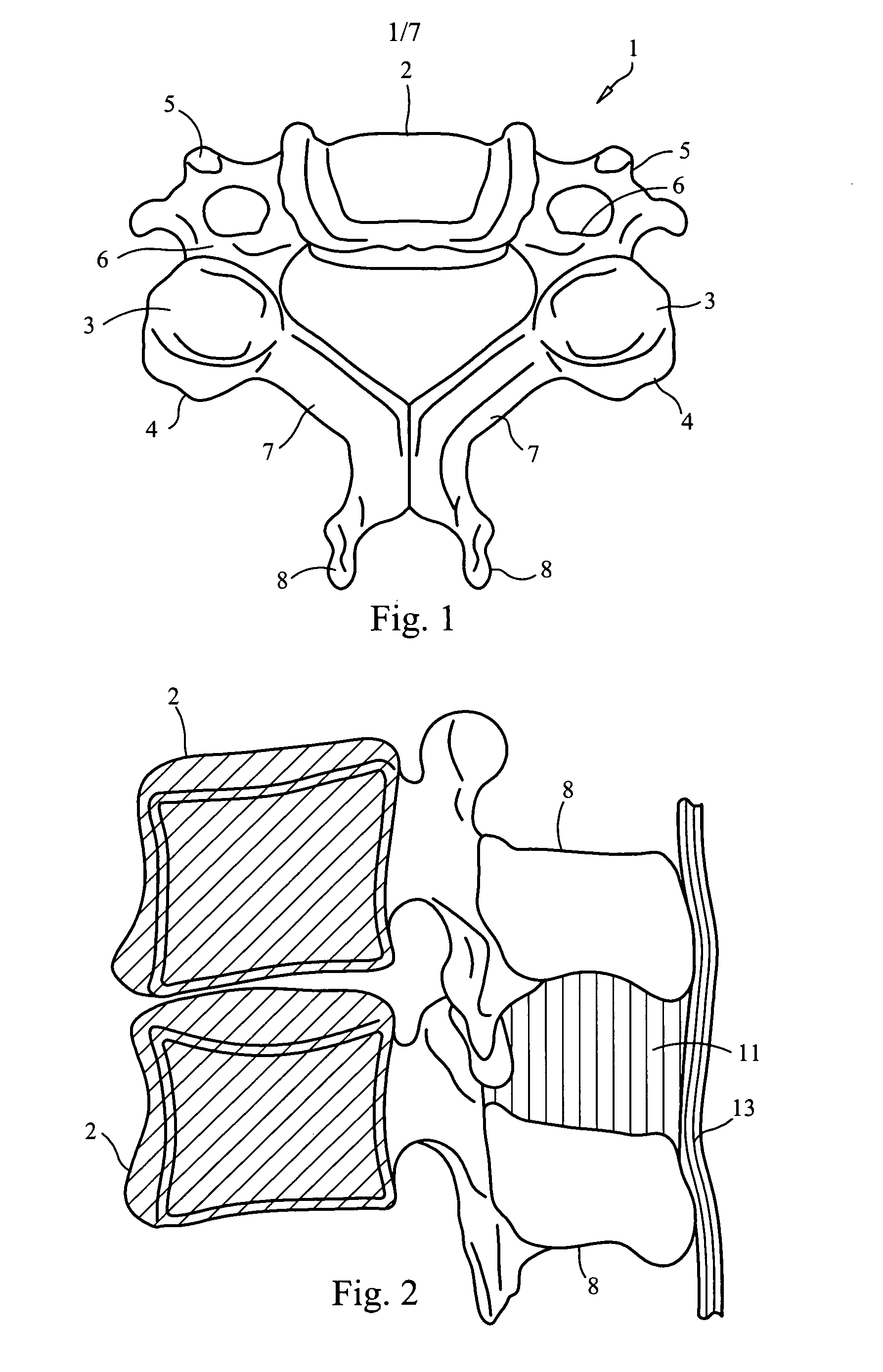
BACKGROUND OF THE INVENTION[0001]With the aging of the population there has occurred an increase in the incidences of degenerative diseases of the spine and this trend is expected to continue with the continuing increase in the percentage of elderly people in the population. Spinal stenosis is one of the most frequent forms of spinal degenerative disease observed. One conventional treatment of spinal stenosis has been laminectomy and decompression of neurologic structures and fusing the treated vertebrae if instability exists. Many potentially negative side effects are inherent in this form of treatment, including profuse bleeding, substantial risk of infection, potential nerve damage sometimes leading to paralysis and / or bladder / bowel dysfunction, dural tears, persistent fluid leakage, arachnoiditis, continuing chronic pain, non-union (if fusion is performed), fusion hardware failure, donor site pain, adjacent segment disease, long operation times, and substantial operation costs.[...

Claims


Application Information

Patent Timeline
IPC IPC(8): A61B17/58A61F2/44
CPCA61B17/7062
Inventor YOUSSEF, JIM A.WANG, JEFFREY CHUNHEWKO, BRIANCANNON, ALAN W.
Owner WANG JEFFREY CHUN
Learn More