Device for injecting high viscosity material

a high-viscosity material and material technology, applied in the field of injection biomechanics, can solve the problems of reducing the pain experienced by patients, increasing the risk of so-called fragility fractures, and losing density and strength of the trabecular bone, and achieving the effects of high viscosity, high viscosity, and high viscosity

Inactive Publication Date: 2008-10-02
GIANNITSIOS DEMETRIOS +2
View PDF57 Cites 24 Cited by
  • Summary
  • Abstract
  • Description
  • Claims
  • Application Information

AI Technical Summary

Benefits of technology

[0017]It is therefore an aim of the present invention to provide a device that provides mechanical advantage for injecting viscous material.
[0020]In accordance with another aspect of the present invention, there is provided a device for injecting high viscosity material, comprising a non-compliant body, a material-moving member separating the non-compliant body into a first cavity having a first volume adapted to receive an incompressible fluid and a second cavity having a second volume adapted to receive a high viscosity material, the material-moving member being displaceable to vary the first and second volumes inversely proportionally, and a pressure applicator for displacing the incompressible fluid into the first cavity that displaces the material-moving member to increase the first volume and decrease the second volume, thereby ejecting the high viscosity material out of the non-compliant body.

Problems solved by technology

Trabecular bone, therefore, loses density and strength and becomes more susceptible to so-called fragility fractures.
Vertebral fragility fractures often occur, resulting in chronic pain, progressive deformity and possibly even neurological deficit or damage.
The cement, once hardened, becomes a permanent reinforcement of the vertebral body and usually drastically diminishes the pain experienced by the patient.
In order to uniformly infiltrate the vertebral body and avoid unwanted leakage, the bone cement needs to have a viscosity preferably more than 100 Pa*s, possibly even more than 300 Pa*s. Injecting low viscosity bone cement can cause cement leakage into the surrounding venous blood vessels, leading potentially to serious complications such as arterial blood pressure drop and / or lung embolism, possibly with fatal outcome.
Immediate abortion of the procedure, if the complication is recognized timely, may limit the damage, but generally does not avoid it.
However, even with the desired bone cement viscosity this method of treatment still has an elevated risk of cement leakage occurring due to the surgeon being distracted from the procedure at hand by the constant demand of changing the syringes.
Still other disadvantages of working with multiple small syringes are that the procedure is time consuming, messy, and filling multiple small syringes ahead of time with cement may cause the syringe nozzle to clog.
In some cases involving high viscosity cement the procedure may have to be abandoned because the injection pressure becomes too great to be manually applied.
Methods and devices have been designed to provide sufficient pressure for injecting relatively viscous bone cements and / or provide sufficient volumes of cement but each with significant disadvantages.
For instance, some devices include hand lever pumps, or power screw designs making them large and bulky.
Although these devices are able to generate the necessary pressures, they are unsuitable for mounting directly atop of a cannula due to existing weight constraints.
Also, the use of larger devices is very cumbersome in a multi-level procedure requiring up to three or four units simultaneously.
The sheer size of these devices makes them impractical to use.
Unfortunately, the friction of the cement flowing through the long small diameter tube is relatively high and therefore much of the force generated by the devices is used to overcome the friction.
Furthermore, the incorporation of a long and reasonably large diameter delivery tube to enable cement flow, and the much higher pressure requirements to overcome additional friction, dramatically limits the tactile feedback for the surgeon.
This limitation is largely due to increased system compliance caused by higher pressures and longer tubing (i.e., the tactile feedback is less direct).
Furthermore, the delivery tube is said to be non-compliant in nature; however, in reality, the compliance disclosed as being present is still too great even at the values specified in the disclosure.
If the system is pressurized to 8274 kPa the compliance of the device can be extremely hazardous to the patient.

Method used


Image

  • Device for injecting high viscosity material
  • Device for injecting high viscosity material
  • Device for injecting high viscosity material

Examples


second embodiment

[0051]FIG. 6 illustrates a second embodiment where the container 12 and the pressure applicator 14 may be connected with an extension line provided as a small inner diameter tube 41 of low compliance that is less than 1 mm in diameter, with thick walls. This embodiment allows the pressure applicator to be removed from the radiation field while maintaining the tactile feedback of the device. The container 12, containing the viscous cement, remains at the closest possible distance from the injection site. As compliance (i.e. of the extension line 41) becomes a greater concern with this embodiment, it is important to have the smallest possible inner diameter for the tube 41 so that the surface tension acting on the tube for any given pressure within the tube is minimal and so that the wall thickness in relation to the tube's inner diameter can be sufficiently larger to minimize compliance.

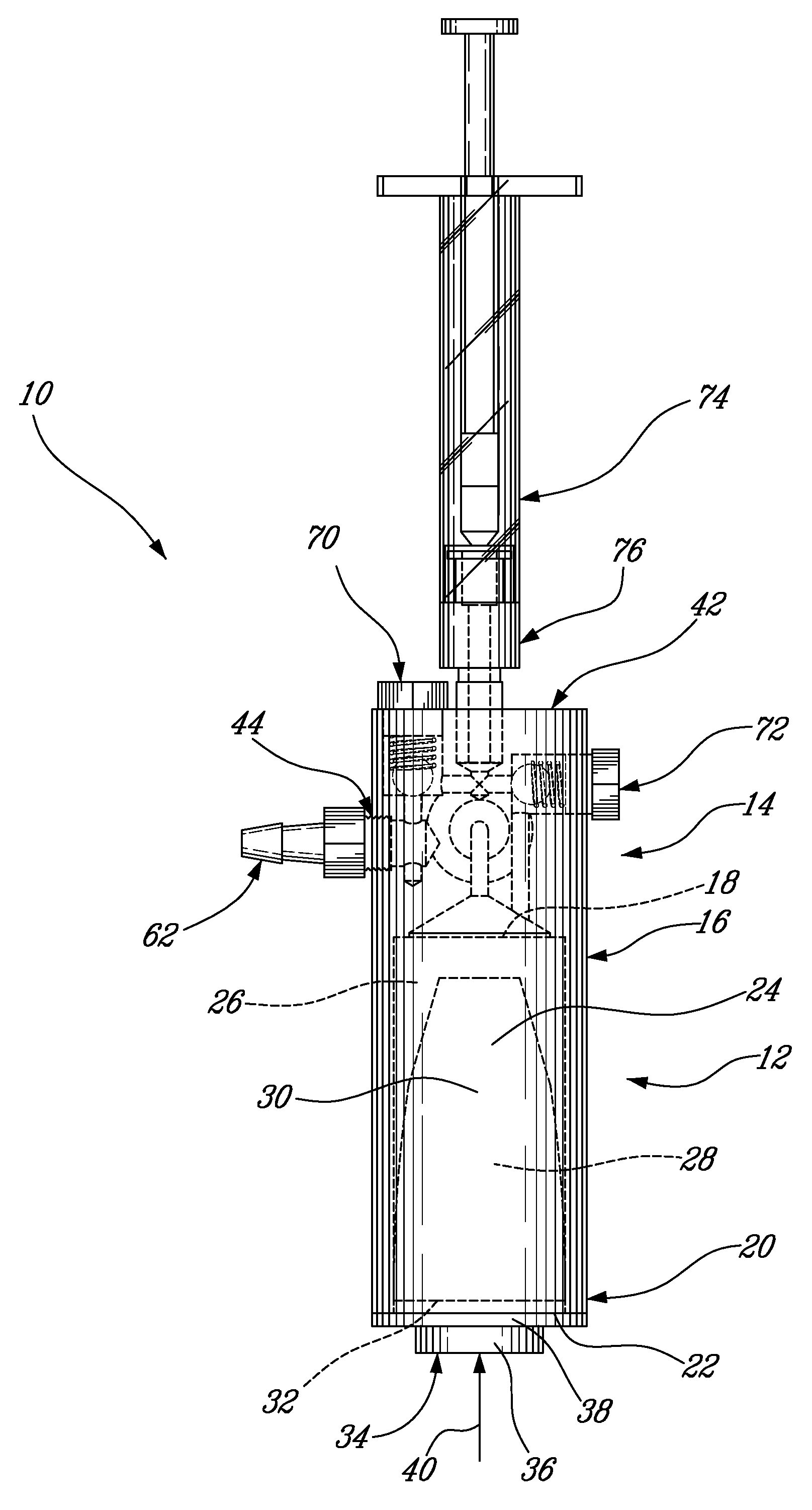
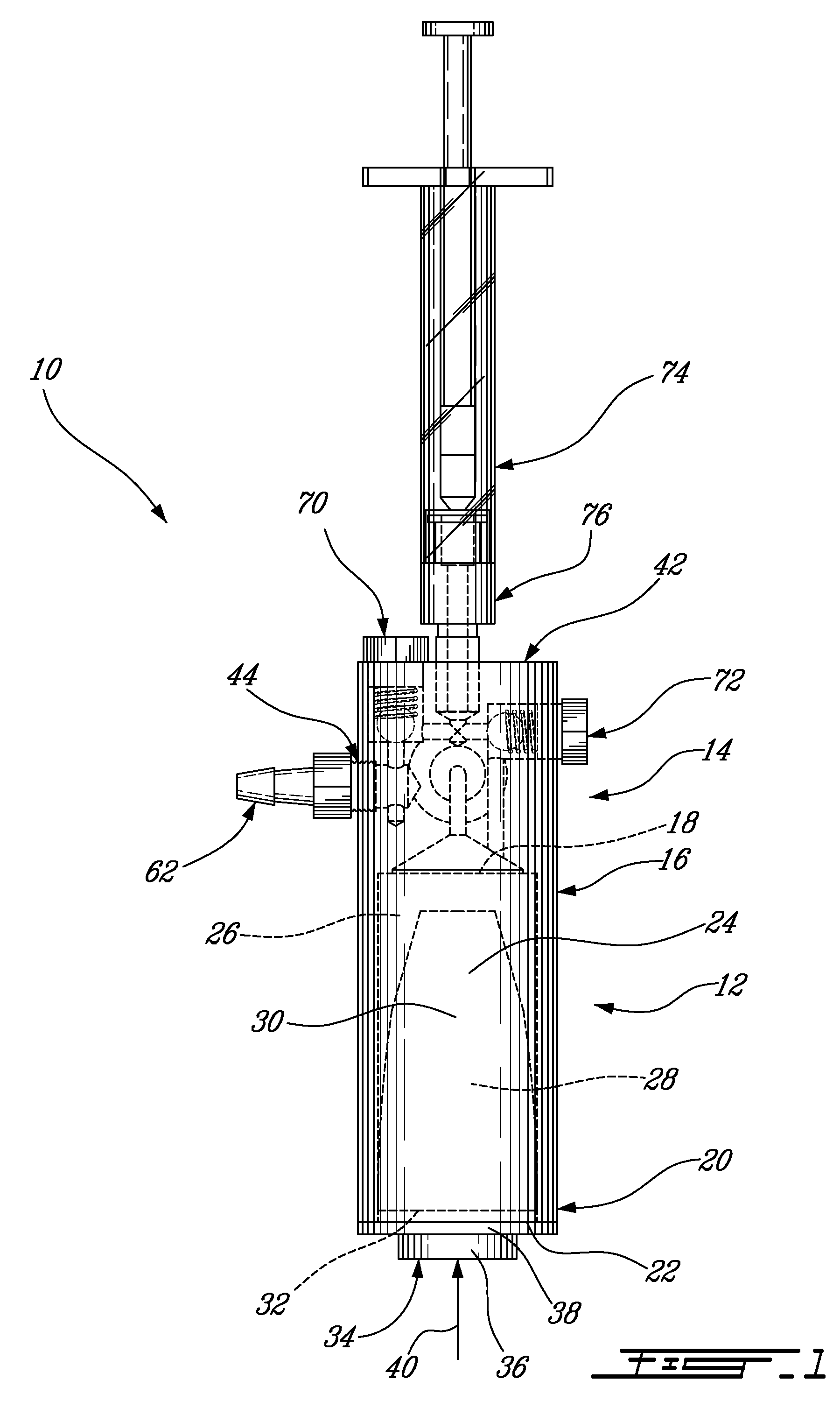
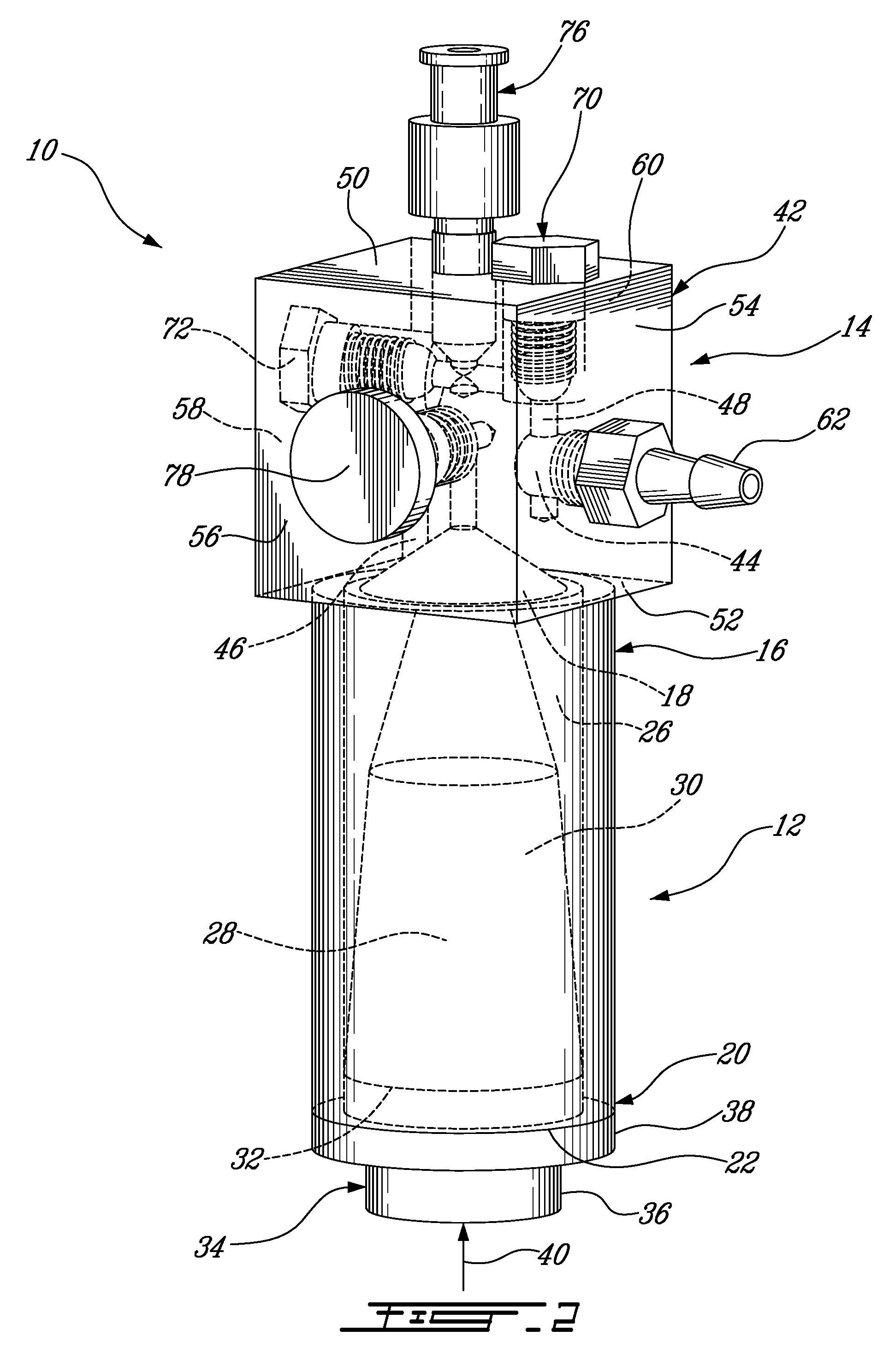
[0052]As best seen in FIGS. 2 and 3, the pressure applicator 14 comprises a housing 42 having a fl...

fifth embodiment

[0067]FIG. 9 illustrates the device 10. Similar reference numerals have been employed to identify like features. In this embodiment the material-moving member is provided as a flexible double membrane identified as 30a and 30b. It can be seen that the flexible membrane 30a is attached to the pressure applicator 14 thereby defining the first cavity 26 adapted to receive the incompressible fluid therein. The flexible membrane 30b is attached proximal to, or at the inlet 18 of, the container 12, thereby defining the second cavity 28 adapted to receive the viscous material in the container 12.

[0068]In operation, the pumping of the power piston 74 (not shown in FIG. 9) will build up a volume of incompressible fluid in the first cavity 26 that will cause the flexible membrane 30a to expand. As the flexible membrane 30a expands, it will push against the flexible membrane 30b thereby causing the latter to apply a pressure against the viscous material in the second cavity 28. Thus, the more ...

eighth embodiment

[0073]FIG. 13 illustrates the device 10, which comprises a temperature control system 108. In this embodiment the container 12 includes inlet and outlet ports 110, 112 as part of the temperature control system 108 for heating or cooling the incompressible fluid. For example, a closed loop fluid circulation system can be used to circulate heated or cooled incompressible fluid in the container without affecting the pressure therein. A radiator or cooling jacket (not shown) can be part of the temperature control system 108 for heating or cooling the circulating fluid. The material-moving member 24 is capable of heat transfer such that the temperature of the viscous material in the container 12 can be controlled. In another example, the container 12 may be provided with a cooling or heating jacket built in the walls thereof. Generally, the temperature control system 108 allows a surgeon to achieve a better control of the viscous material. For example, cooling the viscous bone cement all...


PUM


Abstract

A device for injecting a high viscosity material into a cannula, comprising a container being non-compliant and having an outlet adapted to communicate with the cannula for transferring the high viscosity material thereto, a pressure applicator in fluid communication with the container, the pressure applicator defining a fluid flow path through which an incompressible fluid is displaceable, and a material-moving member interrupting the fluid flow path and defining an incompressible fluid receiving portion on one side thereof in communication with the fluid flow path and a high viscosity material receiving portion in communication with the outlet of the container on an opposed side. The material-moving member being displaceable by a pressure of the incompressible fluid acting thereagainst to force the high viscosity material out of the high viscosity material receiving portion of the container and into the cannula.

Description

CROSS-REFERENCE TO RELATED APPLICATIONS[0001]This is a continuation of International Application No. PCT / CA2006 / 001487 filed Sep. 7, 2006, designating the United States, which itself claims priority on U.S. provisional application 60 / 714,343 filed Sep. 7, 2005, the specifications of both of which are incorporated herein by reference.BACKGROUND OF THE INVENTION[0002]1. Field of the Invention[0003]The present invention relates to the field of injection biomechanics, and more particularly to a device for injecting a high viscosity material to a site within a patient.[0004]2. Description of the Prior Art[0005]Osteoporosis is caused by a gradual loss of bone minerals along with a progressive structural change of trabecular bone (increased porosity, loss of horizontal struts, etc.). Trabecular bone, therefore, loses density and strength and becomes more susceptible to so-called fragility fractures. Vertebral fragility fractures often occur, resulting in chronic pain, progressive deformity...

Claims


Application Information

Patent Timeline
Patent Type & Authority Applications(United States)
IPC IPC(8): A61B17/58B65D25/00
CPCA61B17/8822A61B2017/00539A61F2/44A61M2005/14513A61M5/1483A61M5/445A61F2/4601A61M5/44A61M31/00
Inventor STEFFEN, THOMASBECKMAN, LORNEGIANNITSIOS, DEMETRIOS
Owner GIANNITSIOS DEMETRIOS
Why Eureka
Try Eureka