Optoelectronic device and method of operating optoelectronic device

a technology of optoelectronic devices and optoelectronic devices, which is applied in the direction of lasers, electrical equipment, laser details, etc., can solve the problems of less efficient dbrs, unstable operation, and inability to employ so-called stable resonators on the vertical cavity surface of the emitting laser

Active Publication Date: 2008-10-09
II VI DELAWARE INC
View PDF8 Cites 23 Cited by
  • Summary
  • Abstract
  • Description
  • Claims
  • Application Information

AI Technical Summary

Benefits of technology

[0011]According to the present invention, this problem is solved by an optoelectronic device comprising a substrate, a vertical cavity surface emitting laser formed on the substrate, wherein the vertical cavity surface emitting laser comprises an active layer sandwiched between an output side Bragg mirror and a non-output side Bragg mirror, and such that the intensity of light emitted through the output side Bragg mirror is greater than that emitted through the non-output side Bragg mirror, a light recep

Problems solved by technology

Due to its cavity being formed by plane mirrors generated by DBRs, the vertical cavity surface emitting laser cannot employ so-called “stable resonators” which would require concavely curved mirror surfaces.
Instead, the resonator of the VCSEL is just at the edge of stability, wherein stable operation can only be obtained due to the very short length of the cavity and of the active medium.
Such high levels of spontaneously emitted incoherent light, have a broader bandwidth than the coherently emitted laser light, and thus is less efficiently reflected by the DBRs, providing a high amount of noise and thus a substantial error source for the proper detection of the output power of the las

Method used


Image

  • Optoelectronic device and method of operating optoelectronic device
  • Optoelectronic device and method of operating optoelectronic device
  • Optoelectronic device and method of operating optoelectronic device

Examples


Embodiment Construction

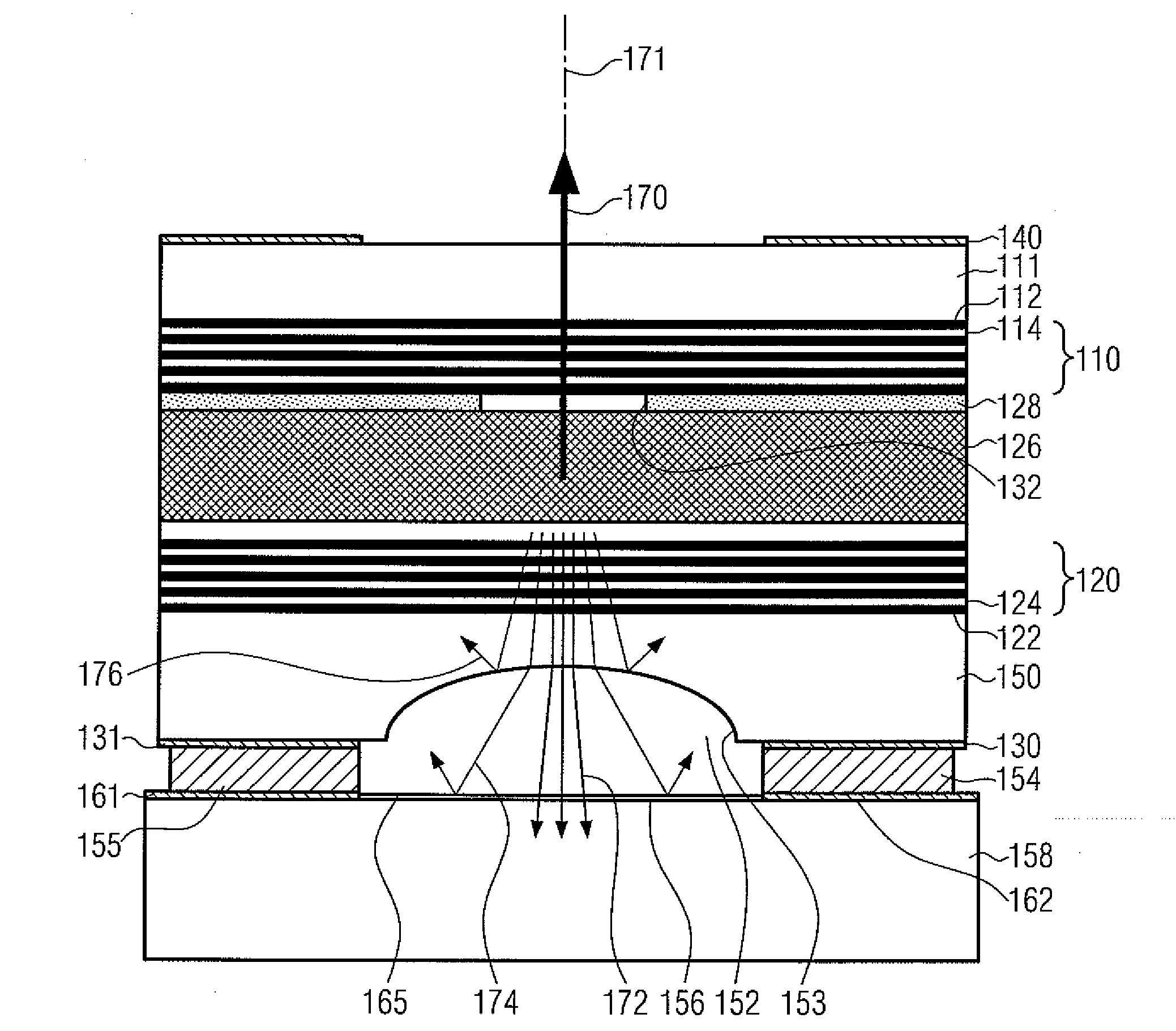
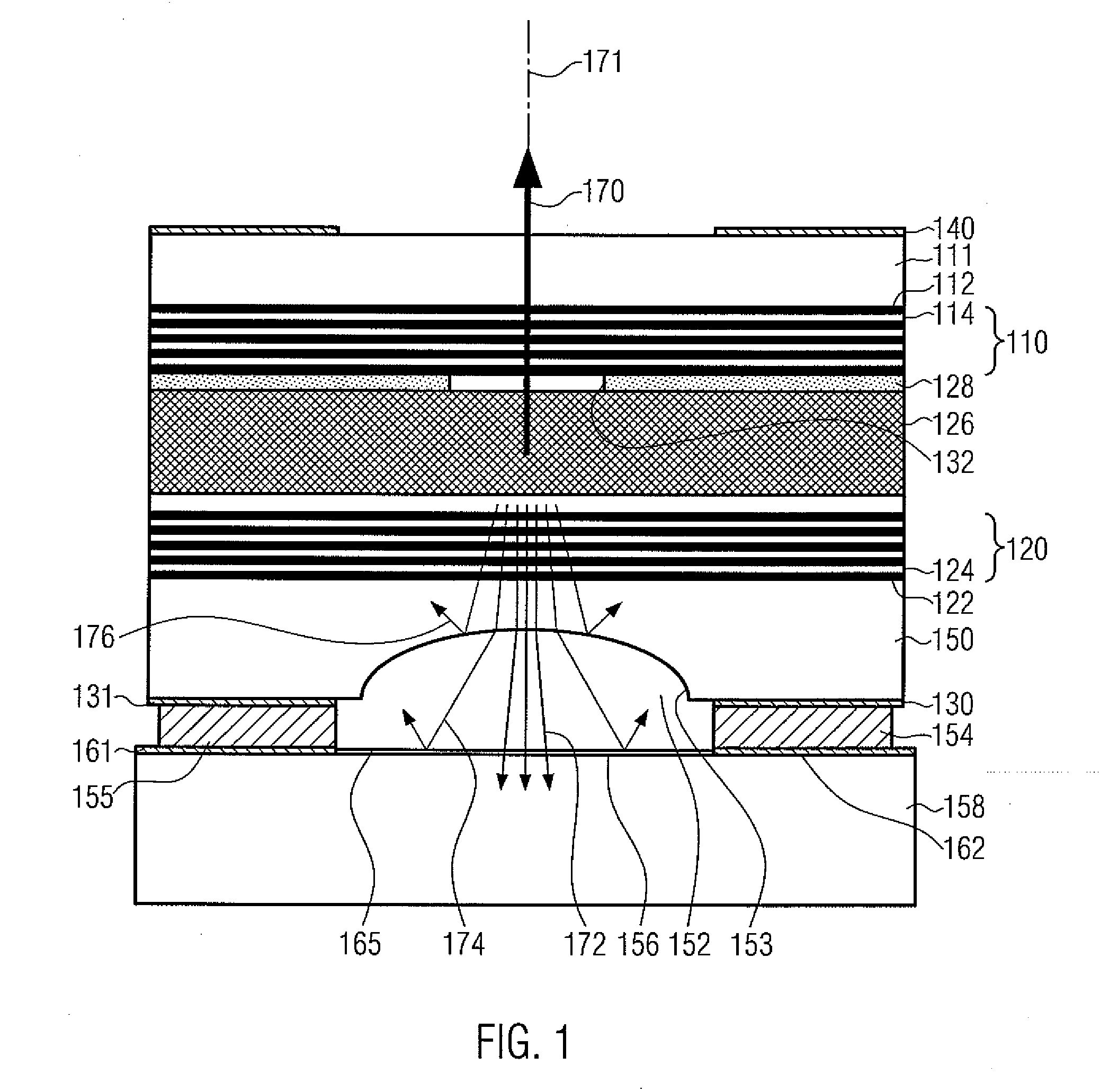
[0031]FIG. 1 shows an optoelectronic device according to the present invention. The optoelectronic device comprises a vertical cavity surface emitting laser (VCSEL) which is formed of an active layer 126 sandwiched between an upper distributed Bragg reflector (DBR) 110 formed of a stack of layers 112 and 114 with different index of refraction, and a lower distributed Bragg reflector 120 formed of another stack of layers of different indices of refraction 122 and 124. An aperture layer 128 is formed between the upper distributed Bragg reflector 20 and the active layer 126. The aperture layer may be formed of a partially oxidized AlGaAs layer. The central unoxidized portion of the AlGaAs layer 128 comprises an electrical aperture 132. The surrounding oxidized portion of the AlGaAs layer 128 comprises an isolation region. This arrangement provides a constriction of the electrical drive current passing through the laser. The aperture 132 has an approximate diameter of about 2 to 20 μm. ...


PUM


Abstract

The invention provides an optoelectronic device combining a vertical cavity surface emitting laser (VCSEL) and a photodetector for monitoring the output power of the vertical cavity surface emitting laser. To improve the signal-to-noise ratio of the photodetector, a light deflector is interposed between the photodetector and the VCSEL.

Description

CROSS-REFERENCE TO RELATED APPLICATION[0001]This application claims priority under 35 U.S.C. §119 to British Patent Application GB 0706584.0, filed Apr. 3, 2007, the entire disclosure of which is incorporated herein by reference.FIELD OF THE INVENTION[0002]The present invention generally relates to optoelectronic devices, and more specifically to optoelectronic devices having a vertical cavity surface emitting laser (VCSEL) using a light receptive device such as a photodiode for light intensity output monitoring.BACKGROUND OF THE INVENTION[0003]Vertical cavity surface emitting lasers are well known to the person skilled in the art. Such lasers have become useful devices for a variety of applications, for instance, in telecommunications, optical property sampling and measurement technology, such as in spectrometers, or in optical position detection devices, such as optical encoders or in optical computer mice.[0004]The VCSEL is a very attractive device for an optical light source sui...

Claims


Application Information

Patent Timeline
IPC IPC(8): H01S5/183
CPCH01S5/0264H01S5/0683H01S5/18311H01S5/18388H01S5/026H01S5/183
Inventor CARTER, ANDREW CANNONMOSER, MICHAEL
Owner II VI DELAWARE INC
Why Eureka
Try Eureka