
Dielectric ceramic composition, complex electronic device and multilayer ceramic capacitor

a technology of electronic devices and capacitors, applied in the direction of fixed capacitors, basic electric elements, electrical apparatus, etc., can solve the problems of inability to ensure reliability, uneven crystalline texture, and large size, and achieve high reliability, good properties, and specific permittivity

Active Publication Date: 2008-10-16
TDK CORPARATION
View PDF10 Cites 23 Cited by
  • Summary
  • Abstract
  • Description
  • Claims
  • Application Information

AI Technical Summary

Benefits of technology

[0009]A purpose of the present invention, reflecting this situation, is to provide a dielectric ceramic composition, showing good properties (specific permittivity, loss Q value, insulation resistance) while a layer can be made thin by relatively decreasing contents of a glass component, etc., and a complex electronic device, such as a multilayer filter, or a multilayer ceramic capacitor, having a dielectric layer constituted by the dielectric ceramic composition.

Problems solved by technology

However, in Japanese Patent No. 3030557, the thickness of a dielectric layer comprised of a dielectric ceramic composition is 50 μm, and therefore, when making the layer thin, the reliability is not be secured.
Also, since the dielectric ceramic composition disclosed in Japanese Patent No. 3030557 includes a relatively high content of a glass component, a grain size may be too large or a crystalline texture may be uneven, so that it is considered difficult to make a layer thin.
Further, when the content of the glass component becomes too large, there is a problem that a plating solution goes into an inside of a body (a multilayer portion) when forming an external electrode as well as a tendency to reduce a specific permittivity.
Also, too large amount of CuO results in segregation, causing a problem to reduce insulation resistance.

Method used


Image

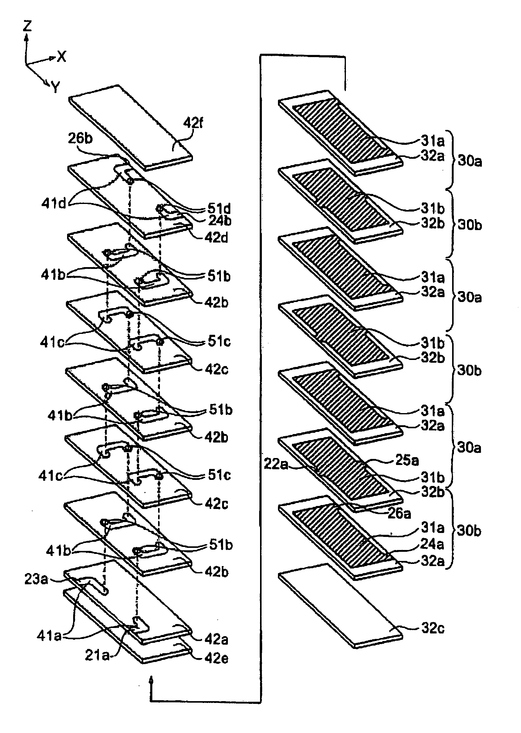
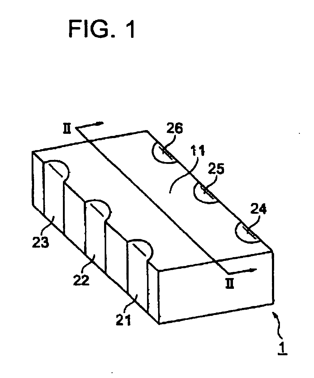
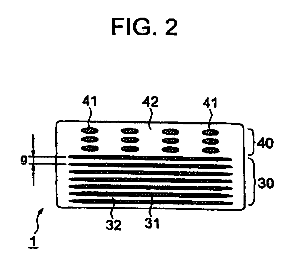
  • Dielectric ceramic composition, complex electronic device and multilayer ceramic capacitor
  • Dielectric ceramic composition, complex electronic device and multilayer ceramic capacitor
  • Dielectric ceramic composition, complex electronic device and multilayer ceramic capacitor

Examples


example 1

[0128]First, SrTiO3 as a main component material constituting a dielectric ceramic composition material and B2O3—ZnO—SiO2-based glass, CuO and MnCO3 as a subcomponent material were prepared. Note that A / B ratio of SrTiO3, i.e. Sr / Ti ratio, was 1.00, and that a glass softening point of the B2O3—ZnO—SiO2-based glass was 630° C. Also, MnCO3 was to be included in a form of MnO in a dielectric ceramic composition after firing.

[0129]Also, as the B2O3—ZnO—SiO2-based glass, a commercial glass was used.

[0130]Note that a composition of the B2O3—ZnO—SiO2-based glass was B2O3:20 wt %, ZnO:65 wt %, and SiO2:15 wt %.

[0131]These materials were weighed and compounded so as to have a composition ratio shown in Table 1 after firing, and wet mixed by a ball mill for 16 hours. After wet mixing, the obtained slurry was dried by a dryer under a condition of 150° C.-24 h, followed by calcine at 800° C. of the dried mixture of powders in a batch furnace to obtain a calcined powder. The calcined powder was ...

example 2

[0142]Except for changing the contents of the glass component and CuO to those shown in Table 2, a dielectric ceramic composition was produced as with Sample 2, and same evaluation was performed as in Example 1. The results are shown in Table 2.

TABLE 2SubcomponentProperties of Sintered BodyB2O3-basedSpecificInsulationglassCuOMnOShrinkageRelativePermittivityResistance ρSample No.(wt %)(wt %)(wt %)FactorDensityεgQ Value(Ω· m)Sample 10Comp. Example1.000.35.1%59.0%754341.3E+07Sample 11Example2.000.317.3%90.4%2085012.3E+10Sample 12Example2.00.50.318.4%97.2%26420391.5E+12Sample 13Example4.500.318.1%92.0%2207056.6E+10Sample 14Example4.50.50.319.0%95.1%23323891.0E+12Sample 15Example4.52.00.319.2%96.8%23514333.1E+11Sample 16Example4.55.00.318.9%97.4%2315539.3E+09Sample 17Example4.510.00.318.7%98.1%2232572.5E+08Sample 18Comp. Example4.512.00.318.7%98.3%2201304.5E+07In Table, “mE + n” means “m × 10+n”.

[0143]From Table 2, compared with Sample 11 and Sample 12, by including CuO, it can be confir...

example 3

[0144]Except for changing the content of MnO to those shown in Table 3, a dielectric ceramic composition was produced as with Sample 3, and same evaluation was performed as in Example 1. The results are shown in Table 3.

TABLE 3SubcomponentProperties of Sintered BodyB2O3-basedSpecificInsulationglassCuOMnOShrinkageRelativePermittivityResistance ρSample No.(wt %)(wt %)(wt %)FactorDensityεgQ Value(Ω· m)Sample 19Example3.01.0019.3%95.9%2444323.9E+11Sample 3Example3.01.00.319.0%95.9%24713371.6E+12Sample 20Example3.01.00.718.9%94.9%23013416.1E+10Sample 21Example3.01.01.518.3%92.6%2063473.4E+09Sample 22Comp. Example3.01.01.818.0%91.7%183885.6E+08In Table, “mE + n” means “m × 10+n”.

[0145]From Table 3, by comparison of Sample 3 with Sample 19, it can be confirmed that inclusion of MnO causes to improve loss Q value and insulation resistance. Also, when the content of MnO is out of the preferable range of the present invention (Sample 22), it can be confirmed that specific permittivity, loss Q...


PUM

PropertyMeasurementUnit
Dielectric polarization enthalpyaaaaaaaaaa

Abstract

The present invention relates to a dielectric ceramic composition comprising a main component including at least one selected from barium titanate, strontium titanate and calcium titanate, and as a subcomponent, a glass component including an oxide of B, wherein a content of said glass component is 2 to 7 wt % with respect to 100 wt % of said main component. According to the present invention, there are provided a dielectric ceramic composition wherein a layer can be made thinner by relatively decreasing a content of the glass component, etc., as well as having good properties (specific permittivity, loss Q value and insulation resistance), and a complex electronic device such as a multilayer filter or a multilayer ceramic capacitor, which has a dielectric layer composed of the dielectric ceramic composition.

Description

BACKGROUND OF THE INVENTION[0001]1. Field of the Invention[0002]The present invention relates to a dielectric ceramic composition sinterable at a low temperature, a complex electronic device and multilayer ceramic capacitor having the dielectric ceramic composition as a dielectric layer.[0003]2. Description of the Related Art[0004]With a demand for reduction in size and weight on an electronic hardware equipped with an electronic device, a demand for small multilayer electronic device is rapidly increased. Also, as a plurality of the electronic devices is placed on a circuit substrate, a multilayer filter as a type of complex electronic devices, wherein a coil and a capacitor is integrated, has been used against a high-frequency noise of the circuit substrate.[0005]Since such a multilayer filter is an electronic device having a coil portion as well as a capacitor portion, in the production process, it is necessary to co-fire a magnetic material constituting the coil portion and a di...

Claims


Application Information

Patent Timeline
IPC IPC(8): C04B35/468C04B35/47C04B35/465H05K1/16H01G4/30
CPCC04B35/465C04B35/4682C04B35/47C04B35/62655C04B2235/3208C04B2235/3215C04B2235/3281C04B2235/3284C04B2235/3409C04B2235/3418C04B2235/365C04B2235/6562C04B2235/6565C04B2235/6567C04B2235/72C04B2235/77C04B2235/9615H01G4/1227H01G4/30H01G4/40H03H1/0007H03H2001/0085C04B35/46C04B35/462C04B35/58C04B2111/90
Inventor KAKUDA, KOUICHISUZUKI, TAKASHITAKANO, SACHIKOMOMOI, HIROSHIKONDO, SHINICHITAKAHASHI, MASAKI
Owner TDK CORPARATION
Learn More