[0004]The object of the invention, therefore, is to propose a truck with a tilting device that is structurally more simple and more resistant relative to collisions, and which is optimized with regard to the
energy absorption in head-on collisions, level with the cab, and the protection of the passengers.
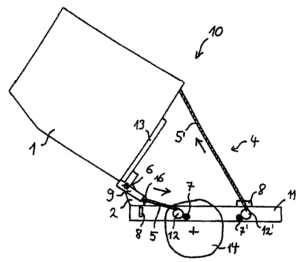
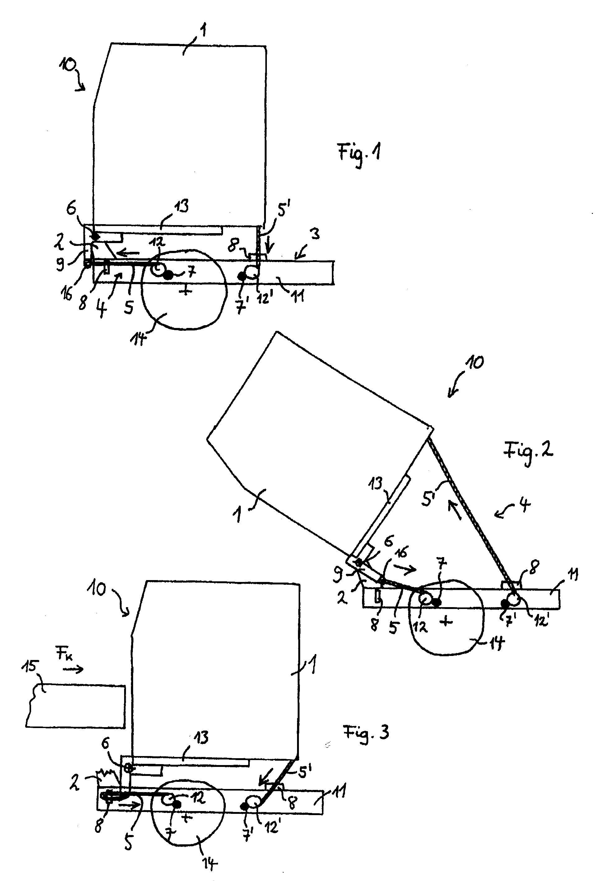
[0006]The truck according to the invention comprises a cab, which is hinged via a bearing to a chassis about a rotational shaft, with a tilting device for raising the cab into a forward-tilted open position for access to the engine compartment located thereunder. The cab is able to be fixed in the closed position to the chassis, and the tilting device comprises at least one tractive element which may be actuated via a drive for raising and closing the cab which is mounted between the cab and the chassis, such that in the case of a head-on collision with an obstruction, level with the cab, it forms a catching device for the cab. The tilting device thus comprises a mechanical tractive element, such as for example a chain, a cable or a belt which may be retracted or released via a drive. The tractive element has the
advantage that, in comparison with hydraulic systems, it requires a small installation space. Greater freedom in the construction and arrangement of components is therefore provided in the
intermediate space between the cab and the chassis. Moreover, in addition to tilting the cab, the tractive element undertakes the function of a catching device for the cab in the event of a
crash. The tractive element is mounted between the chassis and the cab in such a manner that, if the bearing is pulled off, the cab is nevertheless securely fixed. The tractive element holds the cab on the chassis and at least partially converts the
kinetic energy of the
impact as a result of a specific longitudinal extension. The main portion of the energy is diverted into the chassis of the truck. The tilting device formed from at least one tractive element according to the invention thus undertakes a
dual function of allowing the tilting adjustment and the fixing of the cab to the chassis in the event of a
crash. As, due to the tractive element, the complete release of the cab is prevented, excessive damage to the cab is avoided. The tractive element is itself, moreover, not susceptible as regards damage in the event of an accident, as it is designed for a corresponding
tensile strain and allows a specific
relative displacement between the cab and the chassis without being damaged, as would be the case with rigid connections. The tilting device according to the invention is, in particular,
environmentally friendly as it requires no
hydraulic fluid. It may be fitted in a space-saving manner, in particular even in side regions of the truck.
[0011]According to a further advantageous embodiment of the invention, a fixing device is provided for non-positively or positively securing the free length of the at least one tractive element in the closed position of the cab. By securing the free length of the tractive elements, the extension behavior thereof and thus the effectiveness as a catching device are determined. With a greater free length of the tractive elements, the tractive elements may be deformed to a greater extent and may absorb greater amounts of energy in the event of a crash. The securing of the free length of the tractive elements and thus the
extensibility thereof leads to a controlled pulling back of the cab in the event of a head-on collision which involves an at least partial destruction of the energy introduced. The remaining
kinetic energy is then deflected by the tractive elements to the more stable structure of the chassis.
[0013]The fixing device may, according to a further aspect of the invention, preferably be set to a predetermined threshold for yielding in the event of large collision forces. Such a flexible fixing device has the
advantage that, even with large forces, the tractive elements of the tilting and catching device do not tear, so that permanent damage thereof is prevented.
[0014]According to a further advantageous embodiment of the invention, a downwardly projecting L-shaped
coupling part is provided in the region of the rotational shaft of the bearing of the cab to which the tractive element of the tilting device is connected. As a result, complicated deflections of the tractive element are avoided as a point of application is provided below the rotational shaft for a tilting movement introduced by
tractive force. The L-shaped
coupling part forms a type of lever about the rotational shaft of the tilting bearing and is itself fixedly connected to the cab. As a result of the downwardly displaced connection of the tractive element, the tractive element may be aligned in a horizontal plane along the chassis, so that the fixing for the closed position may also be mounted in this region.
[0017]According to a further advantageous embodiment of the invention, the at least one tractive element is adjusted in its
extensibility for catching the cab in the event of a collision. This means in the present case that the tractive element has a sufficient
extensibility, so that in the event of a crash it is able to yield but not tear. The specific extensibility allows a controlled pulling back of the cab relative to the chassis. By the extension of the tractive element, the kinetic energy of the
impact is substantially reduced by deformation. The extensibility of the tractive element is, for example, adjusted depending on the weight, the intensity of front collision forces,
normal load situations and the number of tractive elements.

