Polarizing Plate
- Summary
- Abstract
- Description
- Claims
- Application Information
AI Technical Summary
Benefits of technology
Problems solved by technology
Method used
Image

Examples
example 1
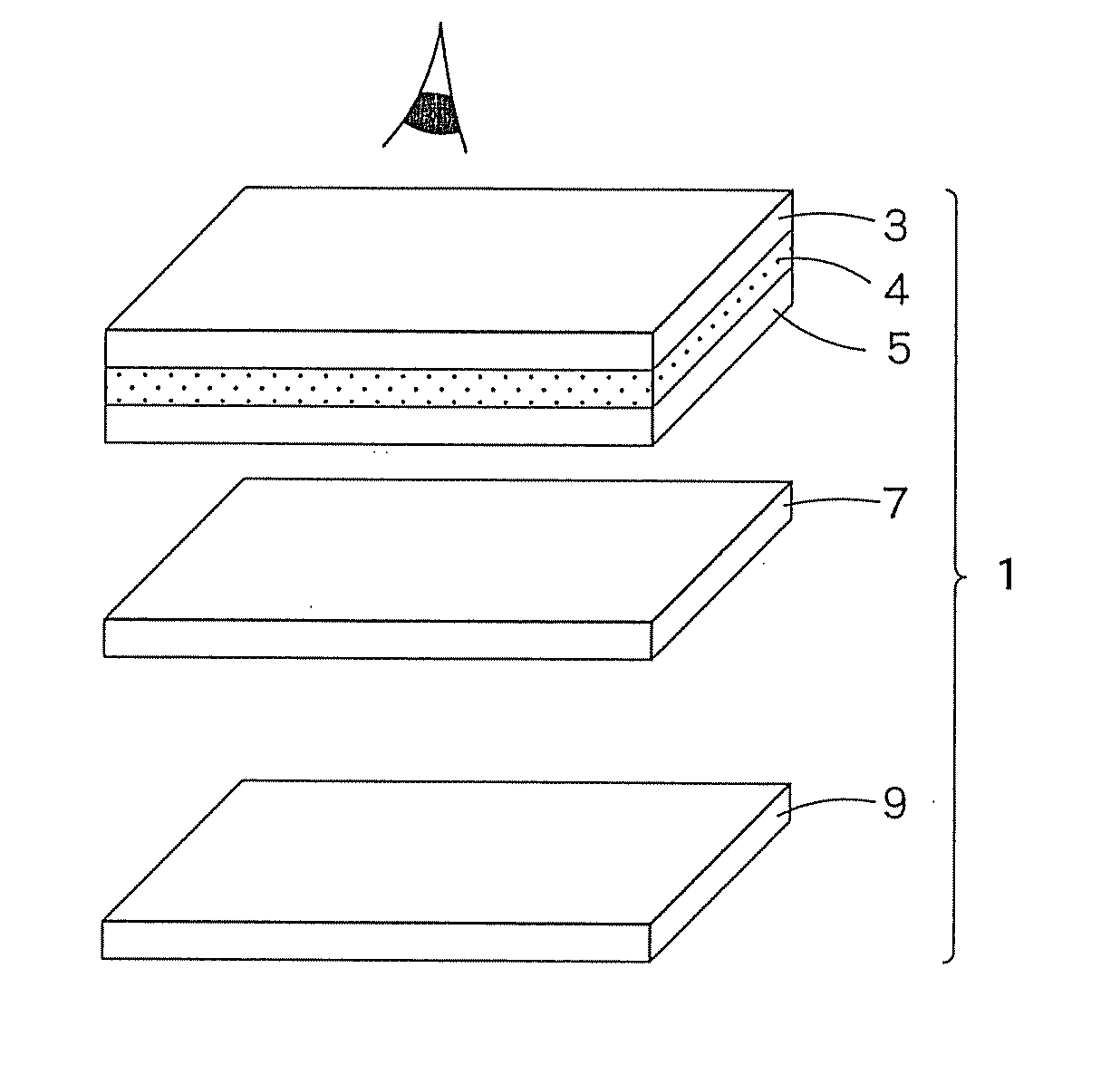
[0189]1) An 80 μm-thick triacetylcellulose (TAC) film (nonstretched base material: first light transparent base material) having a surface subjected to saponification treatment, in which the film was immersed in a 2 mol / liter NaOH (or KOH) solution: 55° C. for 3 min, was washed with water, was subjected to complete removal of water droplets with Kimwipes and was then dried for one min in an oven of 50° C., was provided. Adhesive 1 was coated on the film to a thickness of 100 nm on a dry basis. The coated film was applied to a regulated polarizer. The assembly was dried at 60° C. for 5 min to remove the solvent, whereby a TAC protective film was stacked on one side of the polarizer.
[0190]2) A 100 μm-thick polyethylene terephthalate (PET) film (A4100, manufactured by Toyobo Co., Ltd.) (stretched base material: second light transparent base material) one side of which has been subjected to easy adhesion treatment was provided. Composition 1 for an interface preventive adhesive layer wa...
example 2
[0192]A polarizing plate was produced in the same manner as in Example 1, except that composition 2 for an interface preventive adhesive layer was used instead of composition 1 for an interface preventive adhesive layer, the coverage of the composition 2 for an interface preventive adhesive layer on a dry basis was changed to a thickness of 50 nm, and the assembly was aged at 40° C. for 96 hr. The interface preventive adhesive layer had a refractive index of 1.58, and interference fringes did not occur.
example 3
[0193]A polarizing plate was produced in the same manner as in Example 1, except that composition 3 for an interface preventive adhesive layer was used instead of composition 1 for an interface preventive adhesive layer, the coverage of the composition 3 for an interface preventive adhesive layer on a dry basis was changed to a thickness of 150 nm, and the assembly was aged at 40° C. for 96 hr. The interface preventive adhesive layer had a refractive index of 1.59, and interference fringes did not occur.
PUM
 Abstract
Description
Claims
Application Information
 - Generate Ideas
- Intellectual Property
- Life Sciences
- Materials
- Tech Scout
- Unparalleled Data Quality
- Higher Quality Content
- 60% Fewer Hallucinations
Browse by: Latest US Patents, China's latest patents, Technical Efficacy Thesaurus, Application Domain, Technology Topic, Popular Technical Reports.
© 2025 PatSnap. All rights reserved.Legal|Privacy policy|Modern Slavery Act Transparency Statement|Sitemap|About US| Contact US: help@patsnap.com