Hybrid OLED having improved efficiency
- Summary
- Abstract
- Description
- Claims
- Application Information
AI Technical Summary
Benefits of technology
Problems solved by technology
Method used
Image
Examples
examples
[0249]The following examples are presented for a further understanding of the present invention. During the fabrication of OLEDs, the thickness of the organic layers and the doping concentrations were controlled and measured in situ using calibrated thickness monitors (INFICON IC / 5 Deposition Controller, made by Inficon Inc., Syracuse, N.Y.). The EL characteristics of all the fabricated devices were evaluated using a constant current source (KEITHLEY 2400 SourceMeter, made by Keithley Instruments, Inc., Cleveland, Ohio) and a photometer (PHOTO RESEARCH SpectraScan PR 650, made by Photo Research, Inc., Chatsworth, Calif.) at room temperature. The color was reported using Commission Internationale de l'Eclairage (CIE) coordinates. The explanative examples below help to illustrative the principles and advantages of the invention.
examples 1-2 (
Explanative)
[0250]The preparation of a conventional OLED (Device 1) is as follows: A ˜1.1 mm thick glass substrate coated with a transparent ITO conductive layer was cleaned and dried using a commercial glass scrubber tool. The thickness of ITO is about 22 nm and the sheet resistance of the ITO is about 68 Ω / square. The ITO surface was subsequently treated with oxidative plasma to condition the surface as an anode. A layer of CFx, 1 nm thick, was deposited on the clean ITO surface as the anode buffer layer by decomposing CHF3 gas in an RF plasma treatment chamber. The substrate was then transferred into a vacuum deposition chamber for deposition of all other layers on top of the substrate. The following layers were deposited in the following sequence by evaporation from a heated boat under a vacuum of approximately 10−6 Torr:
[0251]a) an HIL, 10 nm thick, including hexaazatriphenylene hexacarbonitrile (HAT-CN);
[0252]b) a hole-transporting region, 85 nm thick, including N,N′-di-1-naph...
examples 3-4 (
Explanative)
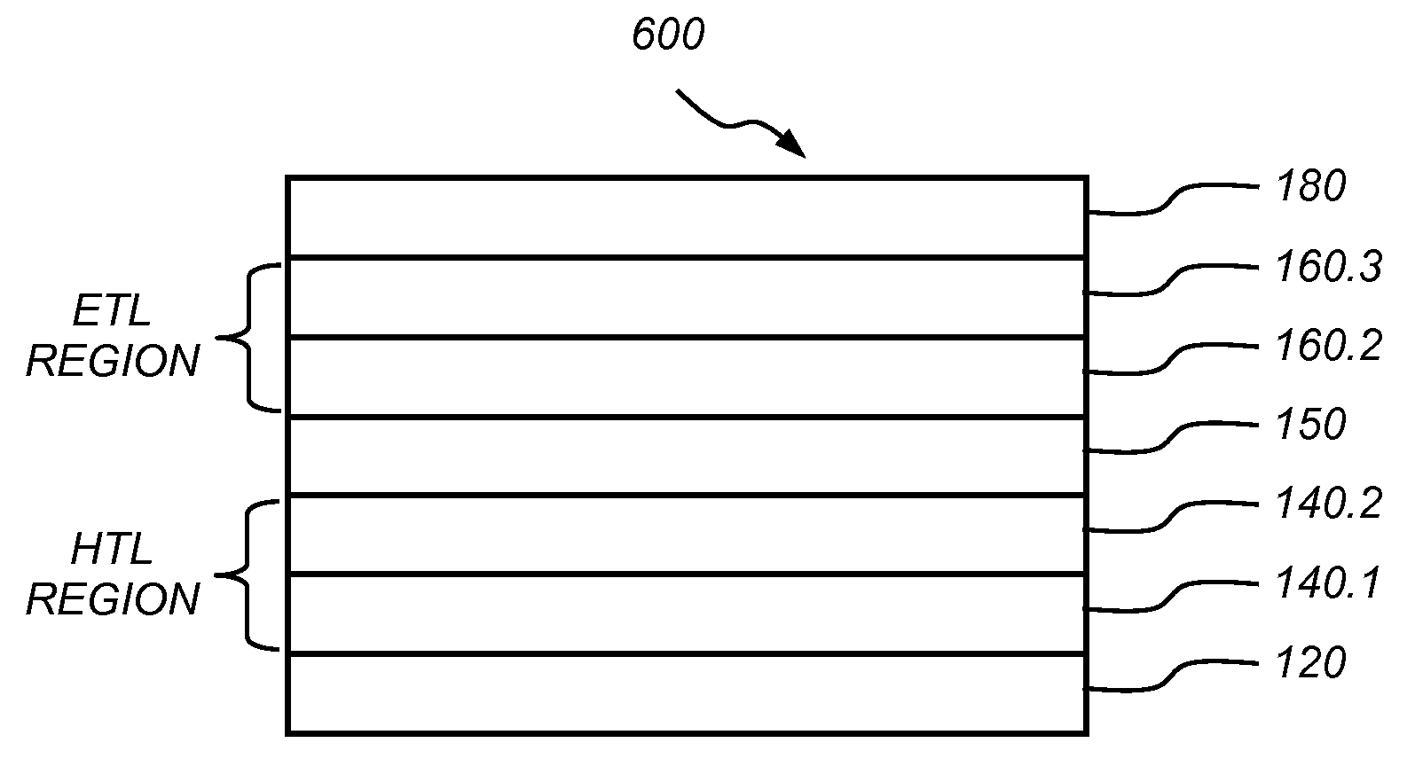
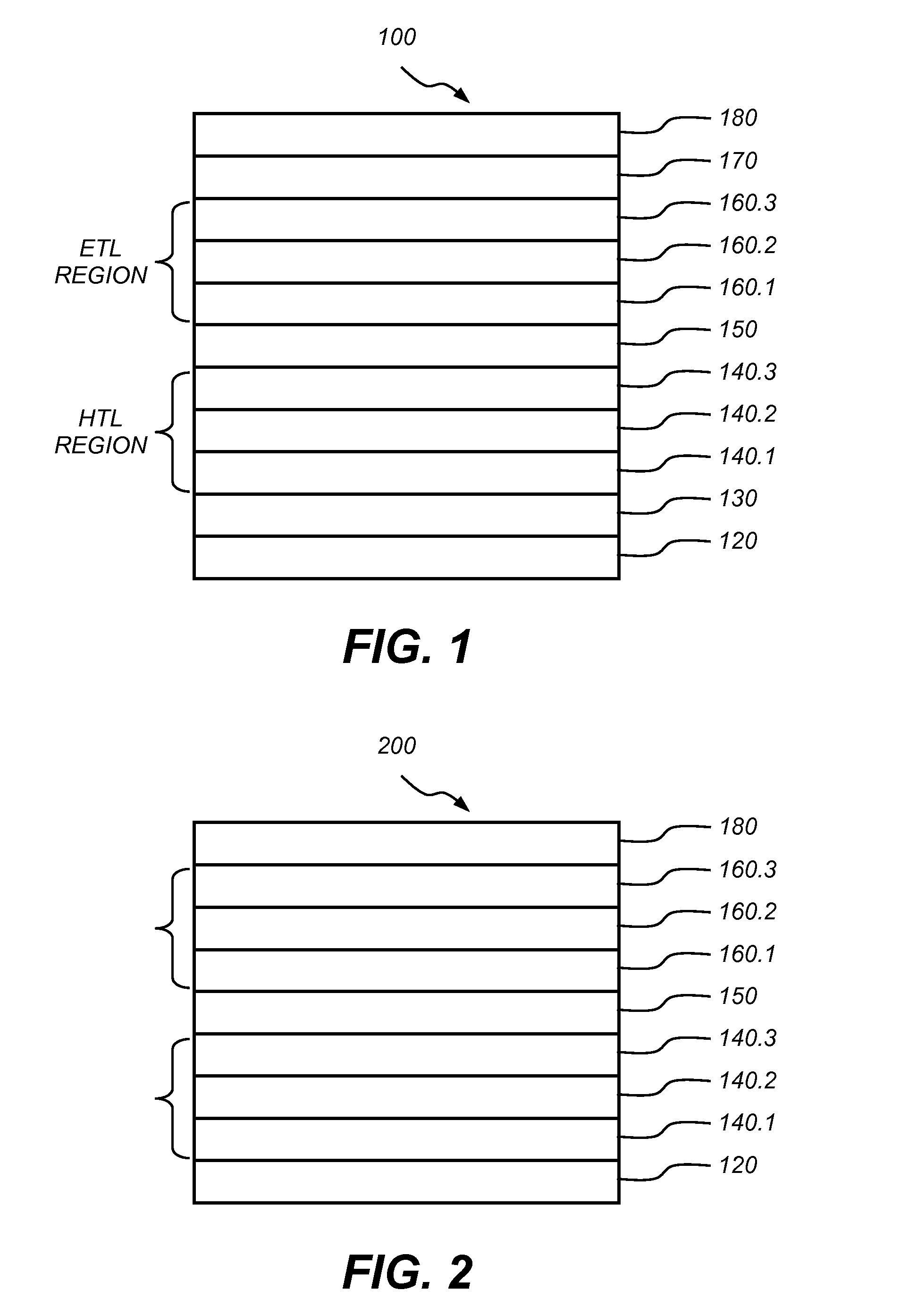
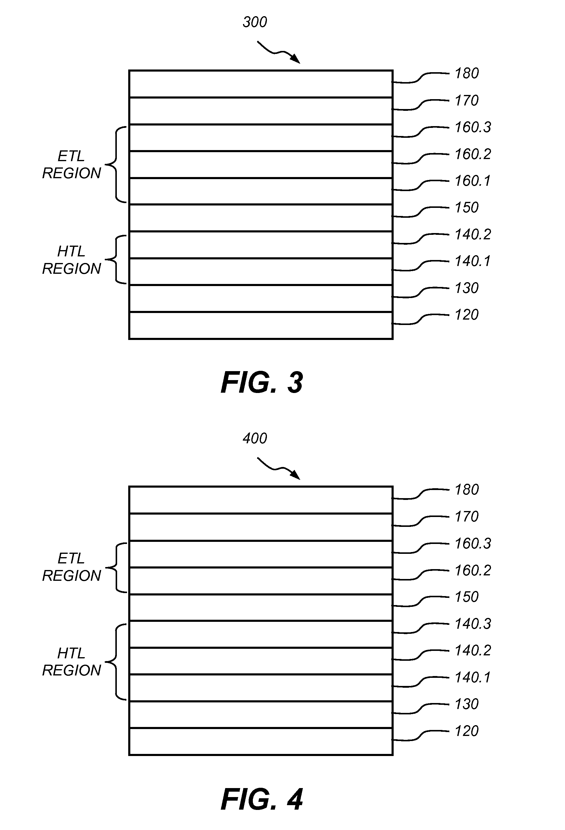
[0266]Another OLED (Device 3) was constructed in the same manner as Example 1. The Layer Structure is
[0267]a) an HIL, 10 nm thick, including HAT-CN;
[0268]b) an HTL, 75 nm thick, including NPB;
[0269]c) a first spacer, 4 nm thick, including 4,4′,4″-tris(carbazolyl)-triphenylamine (TCTA);
[0270]d) a fluorescent blue LEL, 10 nm thick, including 4,4′,4″-N,N-dicarbazole-biphenyl (CBP) as a host and formula (N-7) as a dopant. The doping concentration is about 1.7 vol %.
[0271]e) an electron-transporting region, 34 nm thick, including formula (P-2);
[0272]f) a second ETL, 15 nm thick, including formula (U-3);
[0273]g) an EIL, 2 nm thick, including formula (X-1); and
[0274]h) cathode: approximately 150 nm thick, including Al.
[0275]Device 3 is denoted as: ITO / 10 nm HAT-CN / 75 nm NPB / 4 nm TCTA / 10 nm CBP:1.7 vol % (N-7) / 34 nm (P-2) / 15 nm (U-3) / 2 nm (X-1) / 150 nm Al. The EL performance of the device is summarized in Table 1, and its EL spectrum is shown in FIG. 8.
[0276]Another OLED (Device ...
PUM
 Abstract
Description
Claims
Application Information
 - R&D
- Intellectual Property
- Life Sciences
- Materials
- Tech Scout
- Unparalleled Data Quality
- Higher Quality Content
- 60% Fewer Hallucinations
Browse by: Latest US Patents, China's latest patents, Technical Efficacy Thesaurus, Application Domain, Technology Topic, Popular Technical Reports.
© 2025 PatSnap. All rights reserved.Legal|Privacy policy|Modern Slavery Act Transparency Statement|Sitemap|About US| Contact US: help@patsnap.com


