Method and system for detection of biomaterials using magnetic marker

a biomaterial and magnetic marker technology, applied in the direction of magnetic property measurement, material magnetic variables, instruments, etc., can solve the problems of insufficient detection sensitivity, new problems such as impurities and contamination of containers, and it is extremely difficult to suppress the inclusion of magnetic impurities completely, etc., to achieve easy application, influence of fringing field, and high sensitivity

Inactive Publication Date: 2008-11-20
HITACHI LTD
View PDF5 Cites 10 Cited by
  • Summary
  • Abstract
  • Description
  • Claims
  • Application Information

AI Technical Summary

Benefits of technology

[0024](f) After the external magnetic field for orientation is shut off, the signal of the unbound magnetic marker 4 decays significantly due to the influence of Brownian motion, but the magnetic signals from the specimen are measured in the timing in which the magnetic signals of the bound magnetic markers 3 do not decays significantly. The measurement signal is set as a signal 2. The signal 2 includes the signals of the unbound magnetic markers and the bound magnetic markers of the inversed direction with respect to the signal 1. The signal 2 also includes the magnetic signals from the nonspecific binding magnetic marker 5 and magnetic impurity, but since the external magnetic field for orientation is not so strong as to change the directions of the spins of the magnetic substances included by the nonspecific binding magnetic marker and the magnetic impurity 6, the signals generated by the nonspecific binding magnetic marker and the magnetic impurity and included by the signal 2 are equivalent to these signals generated by the nonspecific binding magnetic marker and the magnetic impurity and included by the signal 1. Accordingly, by subtracting the signal 2 from the signal 1, the magnetic signal components generated by the nonspecific binding magnetic marker and the magnetic impurity fixed to the container can be eliminated.
[0025]As above, according to the present invention, the signals generated by the magnetic substances fixed to the container and the magnetic signals generated by the unbound markers in the solution and unbound markers which are not fixed can be separated. As a result, the influence of the signals of the magnetic impurity of the container and the markers adhered to the container, which is conventionally a problem, can be reduced.
[0026]FIGS. 2A to 2C show an example of a device configuration to which the present invention is applicable. As shown in FIG. 2A, when an external magnetic field for orientation is applied with a magnet 14, and thereafter, the magnetic signal of a specimen 16 is measured with a magnetic sensor 15, the external magnetic field for orientation in the reverse direction can be easily applied by reversing the electric current which is passed to the magnet 14, and the method of the present invention can be applied. As shown in FIG. 2B, magnets 17 and 18 for applying external magnetic fields for orientation with two different polarities are prepared, after the external magnetic field is applied and the specimen is oriented in an certain direction with one magnet 17, the magnetic signals are measured, then, after the external magnetic filed in the reverse direction is appl...

Problems solved by technology

However, in the optical method, the detection sensitivity is not sufficient, and the process of washing the unbound optical marker (washing process) is required.
In the manufacturing process of the container, it is extremely difficult to suppress inclusion of magnetic impurities completely even if the containers are produced with close attention paid to the raw material, production process and the like.
Therefore, impurities and contamination of the container are new problems peculiar to magnetic detection.
Meanwhile, nonspecific binding of markers to the containers also becomes a problem in optica...

Method used


Image

  • Method and system for detection of biomaterials using magnetic marker
  • Method and system for detection of biomaterials using magnetic marker
  • Method and system for detection of biomaterials using magnetic marker

Examples


embodiment 1

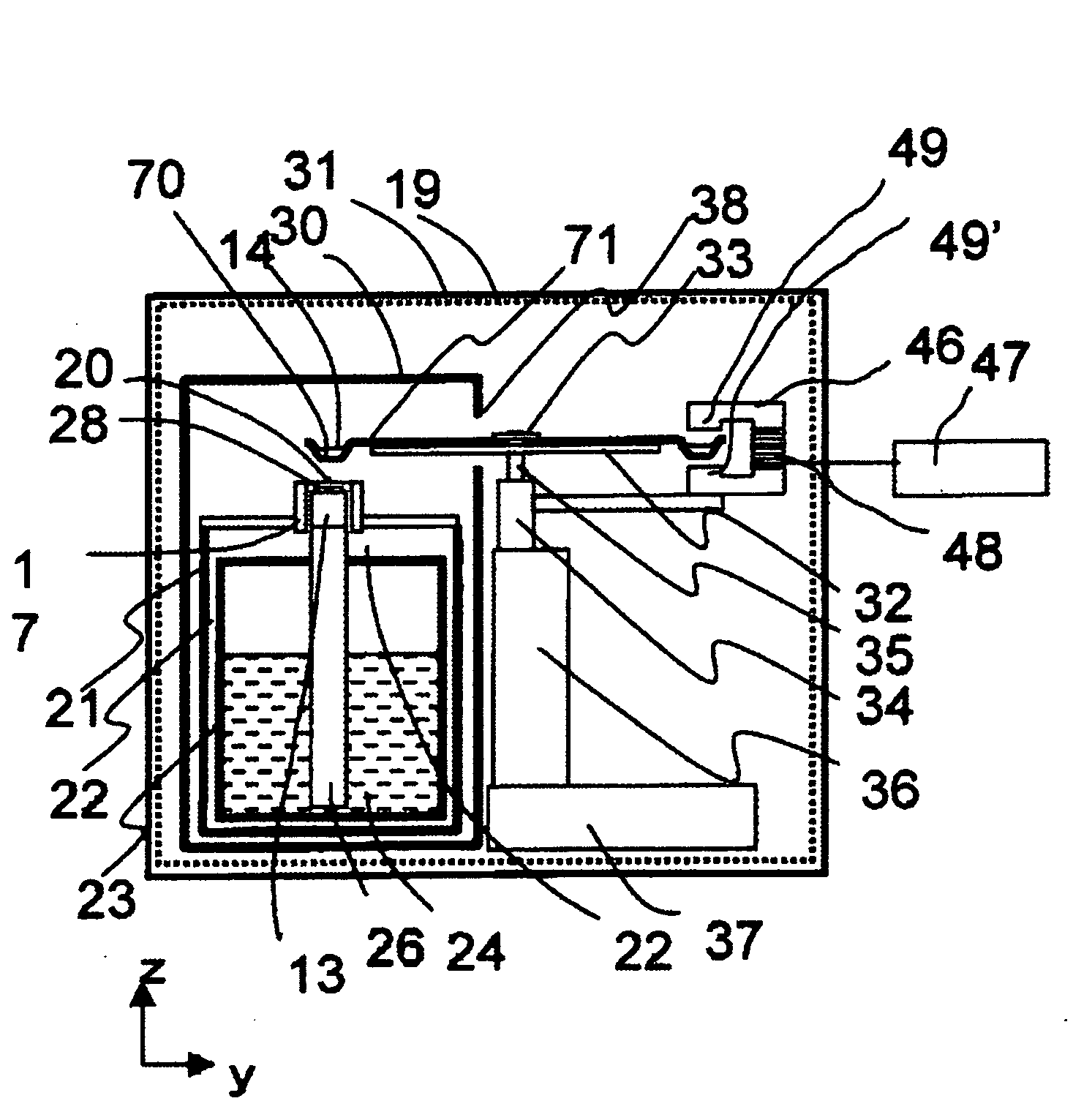
[0043]FIG. 3 is a sectional view showing the configuration of a magnetic bio-inspection system which is one embodiment of the present invention. In order to reduce input of ambient magnetic noise to a SQUID 28, the SQUID and a cooling container 21 for cooling the SQUID are surrounded by an electromagnetic shield 29 and magnetic shields 30 and 31. The magnetic shield 29 is constituted of a metal material with low electric resistance such as aluminum, and the magnetic shields 30 and 31 are constituted of a material with a high magnetic permeability such as permalloy. A cutout hole 38 for inserting a specimen container 71 therein is formed in a part of the magnetic shield 30.

[0044]The specimen container 71 is fixed to a rotating shaft 35 by a fixing screw 33, on a non-magnetic disk-shaped specimen table 32. FIG. 4 shows a schematic view of the specimen container 71 used in the experiment. The container is made of a non-magnetic material such as a resin. The container 71 is circular, ha...

embodiment 2

[0059]In the present embodiment, two magnetizing mechanisms 42 and 43 with reverse polarities from each other are placed on the circumference on which the specimen container 71 rotates as shown in FIG. 10. In embodiment 1, the direction of the external magnetic field for orientation is reversed by disposing the magnetizing mechanism 42 in the vertically inverted position, but in the present embodiment, the direction of the external magnetic field for orientation which is applied to the specimen immediately before measurement can be reversed by reversing the rotating direction of the specimen container 71. The specimen passes through the two magnetizing mechanisms, but the magnetic moments of the specimen are aligned in the direction of the magnetic field of the magnetizing mechanism which the specimen passes immediately before measurement.

[0060]As for the two magnetizing mechanisms 42 and 43, with the position of the SQUID 28 set at zero degrees, the magnetizing mechanism 42 is inst...

embodiment 3

[0062]In the present embodiment, as shown in FIG. 11, on the circumference on which the specimen container 71 rotates, the two magnetizing mechanisms 42 and 43 with reverse polarities from each other are placed, and two SQUIDs 28 and 28′ are further placed. In embodiment 2, by reversing the rotating direction of the specimen container 71 by using the two magnets, the direction of the external magnetic field for orientation which is applied to the specimen immediately before measurement is reversed, but in the present embodiment, by disposing the two magnetic sensors and by rotating the specimen in the arrow direction in FIG. 11, the magnetic signal after passing the magnetizing mechanism 42 can be measured with the SQUID 28, and the magnetic signal after passing the magnetizing mechanism 43 can be measured with the SQUID 28′.

[0063]The magnetizing mechanism 43 has the same structure as the magnetizing mechanism 42, but the direction of its magnetic field is in the reverse direction. ...


PUM


Abstract

Accurate measurement cannot be performed due to magnetic signals from magnetic impurities included in a specimen container. By finding a difference between two measurement signals obtained by applying an external magnetic field for orientation to respective normal and reverse directions, the magnetic signals from the magnetic impurities included in the specimen container which are not dependent on the external magnetic field for orientation can be cancelled. The influence of the magnetic impurities included in the specimen container is reduced, and the signal of the intended bound magnetic marker can be measured with high sensitivity.

Description

CLAIM OF PRIORITY[0001]The present application claims priority from Japanese application JP2007-131203 filed on May 17, 2007, the content of which is hereby incorporated by reference into this application.BACKGROUND OF THE INVENTION[0002]The present invention relates to a system that analyzes biological substances and the like by a magnetic signal by using magnetic nano particles and a magnetic sensor, for example, an immunoassay system used for inspection of, for example, immunoglobulin, hormone, a tumor marker, infectious diseases or the like, a blood culturing device and a bacterial culturing device used for inspection of pathogenic bacterium of an infectious disease, food poisoning and the like.[0003]Inspection of various biological substances (hormone, antibody, antigen, tumor markers and the like), pathogenic bacterium, viruses, cancer cells, DNA, environmentally hazardous materials and the like is possible by using specific binding reaction such as antigen-antibody reaction. ...

Claims


Application Information

Patent Timeline
IPC IPC(8): G01N27/74
CPCG01N33/54333
Inventor TSUKAMOTO, AKIRASUZUKI, DAISUKEKANDORI, AKIHIKO
Owner HITACHI LTD
Why Eureka
Try Eureka