
Device and Method for Destroying Liquid, Powder or Gaseous Waste Using an Inductively Coupled Plasma

a technology of inductively coupled plasma and waste liquid, which is applied in indirect carbon-dioxide mitigation, combustion process, lighting and heating apparatus, etc., can solve the problems of waste disposal, crucial waste processing problem, and uncontrollable manner of waste disposal

Active Publication Date: 2008-11-20
COMMISSARIAT A LENERGIE ATOMIQUE ET AUX ENERGIES ALTERNATIVES
View PDF6 Cites 12 Cited by
  • Summary
  • Abstract
  • Description
  • Claims
  • Application Information

AI Technical Summary

Benefits of technology

[0035]Advantageously, the spraying of water into the gases is carried out before the chemical treatment step of the aforementioned gases is carried out. The aim of this spraying is to lower the temperature of the gas, if necessary.
[0067]The device and process as described in the invention offer flexibility of application in terms of wastes to be processed. Actually, the limit to the introduction of waste materials into the device is due to the fact that it does not accept waste in solid form. All products that can be presented in a liquid or gaseous form, or even in the form of a suspension, can be accepted.

Problems solved by technology

The problem of waste processing has been a crucial problem for the last ten years or so.
In the past most waste was disposed of by being “discharged”, usually in an uncontrolled manner.
Now, however, changes in the nature and quantities of waste mean that an industrial approach to the treatment of waste is required.
The efficiency is reduced, however, due to the fact that the feed to be destroyed does not pass inside the torch.
The destruction of liquid products proves to be more complicated due to the difficulty of mixing a liquid phase homogenously with a high-temperature, high-velocity gas phase emerging from a blown arc plasma torch.
This difficulty further reduces the thermal performance and efficiency of the process.
This leads to highly reducing gases being produced which must be burnt at the torch outlet before being discharged into the atmosphere.
The introduction of two phases (liquid and gaseous) in this type of technology does not facilitate the achievement of stable operating conditions.
It is therefore not possible to process liquids directly without vaporising them beforehand in a traditional incinerator, for example, as described in this document.
In addition, the fact that the feed is not introduced into the torch itself (for reasons of incompatibility of material) greatly reduces the efficiency of the process.
The field temperature achieved (300-1000° C.) does not allow destruction in the strict sense of the term to take place, but rather produces correct conditions for separation of the various components.

Method used


Image

  • Device and Method for Destroying Liquid, Powder or Gaseous Waste Using an Inductively Coupled Plasma
  • Device and Method for Destroying Liquid, Powder or Gaseous Waste Using an Inductively Coupled Plasma
  • Device and Method for Destroying Liquid, Powder or Gaseous Waste Using an Inductively Coupled Plasma

Examples


Embodiment Construction

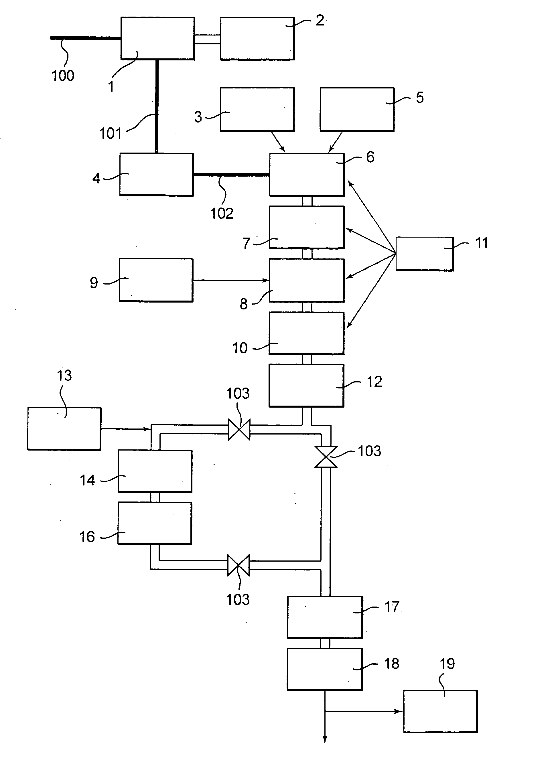
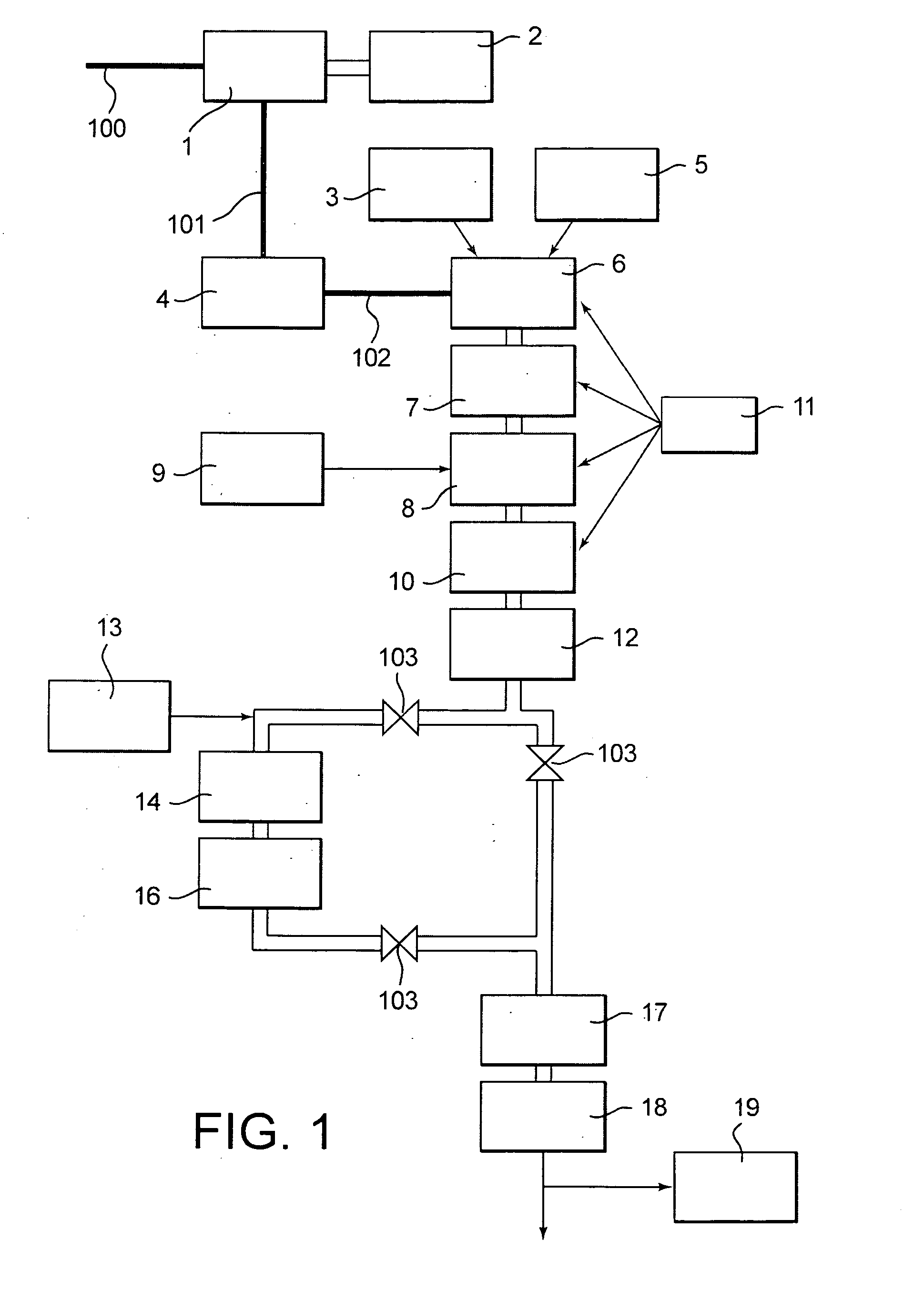
[0074]The installation used for the thermal destruction process as described in the invention is described in FIG. 1.

[0075]An electrical generator 1 connected to a 380V / 50 Hz electricity supply system (reference 100) and cooled by a cooling plant 2, supplies a plasma torch 6 with a high frequency supply through a control panel 4. This control panel may be, for example, a tuning cabinet. Reference 101 represents the coaxial cable connecting the electrical generator 1 to the control panel 4, and reference 102 illustrates an induction arm connecting the panel 4 to the plasma torch 6.

[0076]The plasma torch 6 must be supplied with gas in order to operate. The introduction of these operating gases 3 as well as the introduction of the water / waste mixture to be processed 5 occurs directly inside the torch 6. The water and waste are mixed together beforehand, ant then the mixture is introduced into the torch 6 using a spray probe for liquids or suspensions and using an injection probe for ga...


PUM

PropertyMeasurementUnit
temperatureaaaaaaaaaa
temperaturesaaaaaaaaaa

Abstract

The invention relates to a thermal destruction process for at least one organic or halogenated organic product in liquid, gaseous or powder form. The process includesmixing:of the aforementioned one or more organic products with water in sufficient quantities to ensure that at least stoichiometric ratios between atoms of carbon and oxygen in the mixture are obtained, orof the aforementioned one or more halogenated organic products with water in sufficient quantities to ensure that at least the stoichiometric ratios for, on the one hand, atoms of carbon and oxygen in the mixture, and on the other hand, for hydrogen and halogen atoms in the mixture are obtained,introduction of this mixture and of plasmagenic gases into the coil of an inductively coupled plasma torch to produce gas in which decomposition into atomic elements has occurred,an initial thermal destruction operation of the aforementioned gas in which decomposition into atomic elements has occurred, this initial destruction operation taking place in a reaction chamber,a second thermal destruction operation of the gas that has undergone the initial destruction operation, this second destruction operation taking place in a stirring device with no energy being added, this gas which undergoes the second thermal destruction operation being stirred with air and / or oxygen,recombination by cooling of at least a part of the gas emerging from the stirring device,discharge of the gas that has been destroyed.The invention also relates to a device that allows this destruction process to be applied.

Description

TECHNICAL FIELD[0001]This invention relates to a device and a process for the destruction of toxic or hazardous chemical products using inductively coupled plasma. These products may occur in liquid, gaseous or powder form and belong to the family of organic or halogenated organic compounds.PRIOR ART[0002]The problem of waste processing has been a crucial problem for the last ten years or so. In the past most waste was disposed of by being “discharged”, usually in an uncontrolled manner. Now, however, changes in the nature and quantities of waste mean that an industrial approach to the treatment of waste is required.[0003]Numerous processing technologies have been implemented for the treatment of waste, so that development can still occur without causing damage to the environment. These highly effective technologies for the destruction of waste all have in common to offer, at the same time, a process for the destruction of waste, for the processing of the fumes produced by this dest...

Claims


Application Information

Patent Timeline
Patent Type & Authority Applications(United States)
IPC IPC(8): B01J19/08H05H1/26F23G5/10F23G5/02F23G5/08F23G5/14H05H1/30
CPCF23G5/02F23G5/085F23G5/14Y02E20/344F23G2209/142F23L2900/07005H05H1/30F23G2204/201Y02E20/34
Inventor MEILLOT, ERICKGUENADOU, DAVID
Owner COMMISSARIAT A LENERGIE ATOMIQUE ET AUX ENERGIES ALTERNATIVES
Learn More