Method for depositing electrically insulating layers

a technology of electrical insulation and layer, which is applied in the direction of plasma technique, vacuum evaporation coating, coating, etc., can solve the problems of constant discharge voltage, unstable discharge voltage, and breakdown

Active Publication Date: 2008-11-20
OERLIKON TRADING AG TRUEBBACH
View PDF11 Cites 16 Cited by
  • Summary
  • Abstract
  • Description
  • Claims
  • Application Information

AI Technical Summary

Problems solved by technology

In the process, for instance when a square pulse shape is produced, there will be a very transient increase in the discharge voltage which, however, cannot be held constant but will break down, since due to the low plasma impedance in the spark discharge the spark current promptl

Method used


Image

  • Method for depositing electrically insulating layers
  • Method for depositing electrically insulating layers
  • Method for depositing electrically insulating layers

Examples


Embodiment Construction

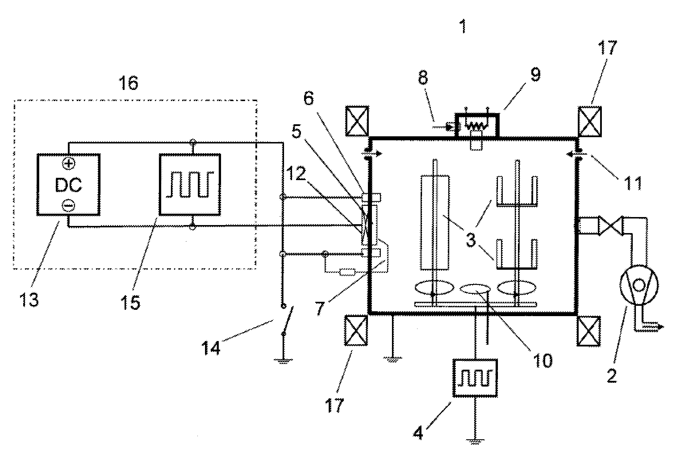
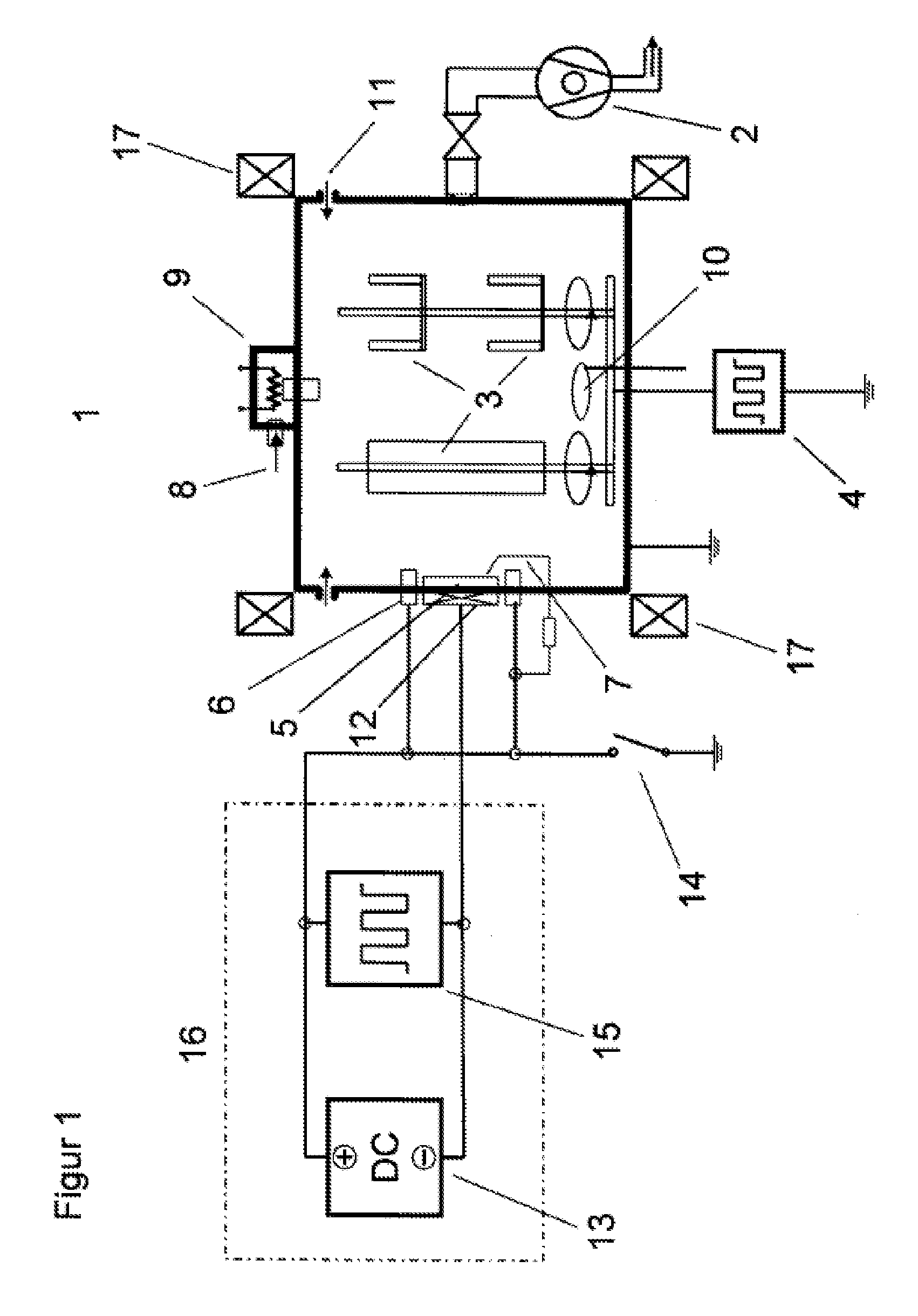
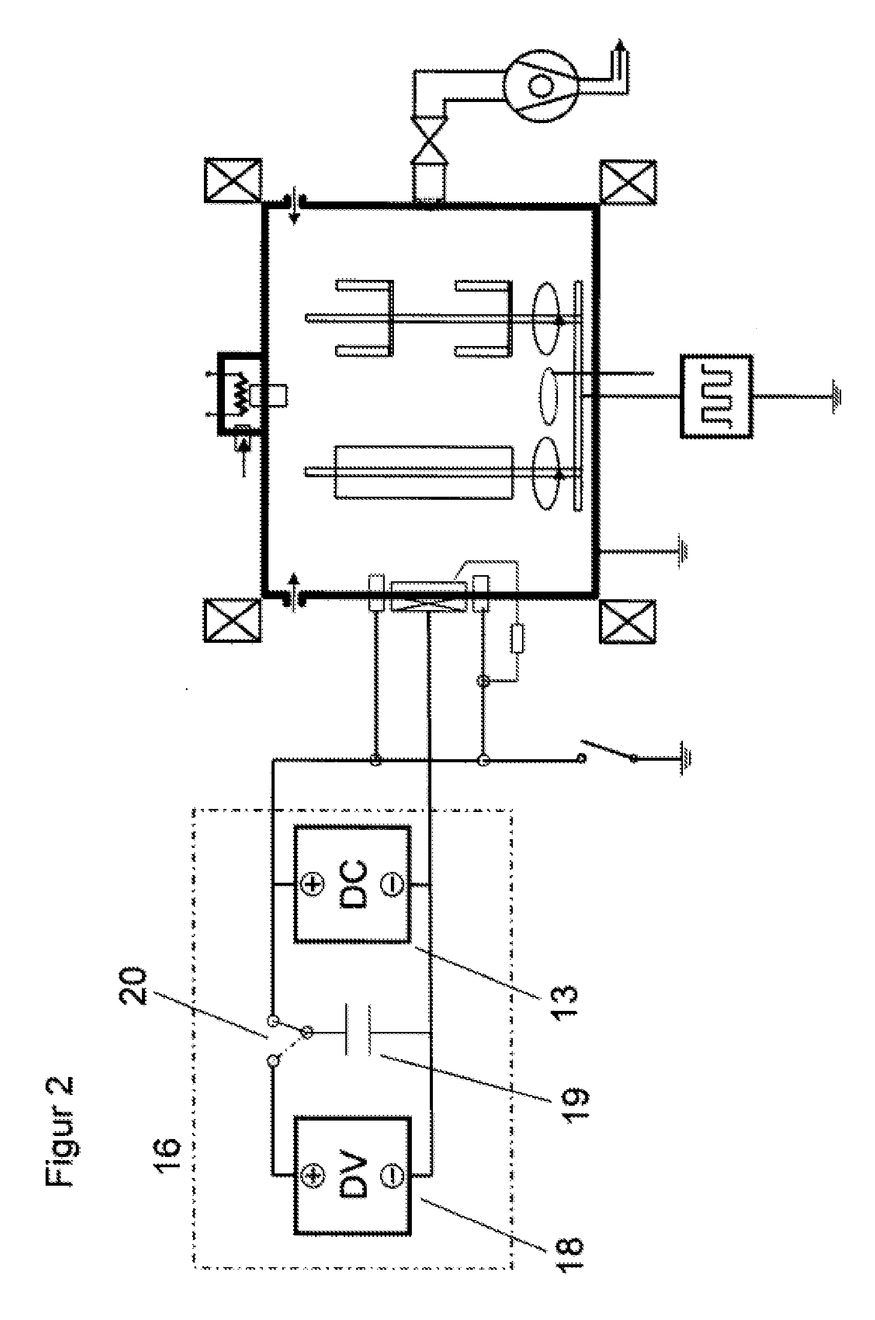
[0006]It is the objective of this invention to introduce a method that avoids the above-mentioned shortcomings of prior art while making it possible to combine the advantages of the high ionization rate of a spark discharge with the advantage of an augmented discharge voltage without exposing the spark cathode, in particular the surface of the spark cathode, to a thermal overload. The invention achieves this objective through the characterizing features specified in claim 1.

[0007]Accordingly, an electric spark discharge is ignited and maintained on a target surface and is simultaneously operated with a direct current and a relatively low constant voltage from a power supply. At the same time, a pulsed current generated by a periodically applied voltage signal is introduced, with the shape of the voltage signal being in essence arbitrarily selectable.

[0008]Basically, there are different ways in which the spark current can be pulsed, thus increasing the spark discharge voltage.

[0009]U...


PUM

PropertyMeasurementUnit
Fractionaaaaaaaaaa
Timeaaaaaaaaaa
Timeaaaaaaaaaa

Abstract

The invention relates to a method for operating an arc source, whereby an electric spark discharge is ignited and run on the surface of a target and the spark discharge is simultaneously fed a direct current with an associated constant voltage DV as well as a pulsed current generated by a periodically applied voltage signal. The voltage at the arc source is boosted over several microseconds and the shape of the voltage signal is in essence arbitrarily selectable.

Description

[0001]This application is a continuation-in-part of application Ser. No. 11 / 548,529 filed Oct. 11, 2006 the entire content of which is incorporated herein by reference.TECHNOLOGY[0002]This invention relates to a method for operating an arc source as conceptually specified in the claims.PRIOR ART[0003]Prior art describes various methods for operating arc sources, also referred to as arc evaporation sources or spark evaporators, employing the combination of a DC power supply and a pulsed-current power supply.[0004]EP 0 666 335 B1, for example, proposes a method whereby for the evaporation of highly conductive materials by means of a direct current-operated arc evaporator a pulsed current is superimposed. Pulsed currents of up to 5000 A are generated, at relatively low pulse frequencies within a range from 100 Hz to a maximum of 50 kHz, by capacitor discharges. In the evaporation process of purely metallic targets this is said to also result in a significantly reduced droplet formation...

Claims


Application Information

Patent Timeline
IPC IPC(8): H01T14/00
CPCC23C14/0021C23C14/08H01J37/32064C23C14/325H01J37/32055C23C14/081
Inventor RAMM, JURGENWOHLRAB, CHRISTIAN
Owner OERLIKON TRADING AG TRUEBBACH
Why Eureka
Try Eureka