Cutting Tool for High-Quality High-Efficiency Machining and Cutting Method Using the Same

Active Publication Date: 2008-11-27
SUMITOMO ELECTRIC HARDMETAL CORP
View PDF11 Cites 32 Cited by
  • Summary
  • Abstract
  • Description
  • Claims
  • Application Information

AI Technical Summary

Benefits of technology

[0013]The cutting tool according to the present invention has superfinishing cutting edges which have both the cutting function and burnishing function. The superfinishing cutting edges remove a affected layer formed by the finishing cutting edge, and simultaneously burnish the surface of the workpiece, thereby applying compressive residual stress to the finished surface.
[0014]Further, like the major cutting edge of the tool disclosed in Patent document 1, the superfinishing cutting edges are cut into the workpiece until their depth of cut exceeds that of the finishing cutting edge to remove a affected layer. The superfinishing cutting edges have burnishing portions extending in the feed direction of the tool and having a large width. Thus, feed marks formed on the finished surface by the superfinishing cutting edges are small compared to the tool of Patent document 1. This makes it possible to improve the machining efficiency by increasing the depth of cut of the superfinishing cutting edges and the feed rate of the tool, or to suppress the formation of a affected layer by reducing the load on (i.e. depth of cut of) the finishing cutting edge.
[0015]Due to these advantages, well-balanced, efficient machining of a workpiece is possible. The machined surface has improved surface roughness with a affected layer sufficiently removed and compressive residual stress applied thereto. The machined surface can thus be finished to a high quality.
[0016]The present invention is applicable to a cutting tool for machining aluminum and aluminum alloy (in which case the hard members involved in cutting are preferably made of sintered diamond). But advantages of the invention will be especially marked if the concept of the present invention is applied to a cutting tool for machining hardened steel.
[0017]In the tool used to cut hardened steel, if the amount of projection B of the superfinishing cutti

Problems solved by technology

But in this arrangement, the shape of the minor cutting edge tends to be transferred onto the finished surface in the form of corrugated feed marks, thus detrimentally influencing the surface roughness of the finished surface.
Although the surface roughness of the finished surface can be improved by reducing the depth o

Method used


Image

  • Cutting Tool for High-Quality High-Efficiency Machining and Cutting Method Using the Same
  • Cutting Tool for High-Quality High-Efficiency Machining and Cutting Method Using the Same
  • Cutting Tool for High-Quality High-Efficiency Machining and Cutting Method Using the Same

Examples


example 1

[0064]Cutting tool samples No. 1 to No. 42 shown in Tables 1A and 1B were prepared and evaluated for their cutting performance. Cutting tool samples No. 1 to No. 42 are formed of cBN-based sintered members of which the portions used for cutting have different shapes from each other. The cBN-based sintered members of each tool were formed by mixing cBN powder with binder powder comprising TiN and Al in a ball mill made of cemented carbide, and sintering the mixture in an ultrahigh pressure apparatus under a pressure of 5 GPa at 1500° C. Such cBN-based sintered members contained 60% by volume of cBN particles having an average particle diameter of 3 μm, the balance being Ti compounds primarily comprising TiN, Al compounds such as nitrides, borides or oxides of Al, and trace amounts of W and / or Co compounds.

[0065]Any of the cutting tools used in this evaluation test comprised a substrate made of cemented carbide, and cBN-based sintered members each having a thickness of 1.8 mm, a nose ...

example 2

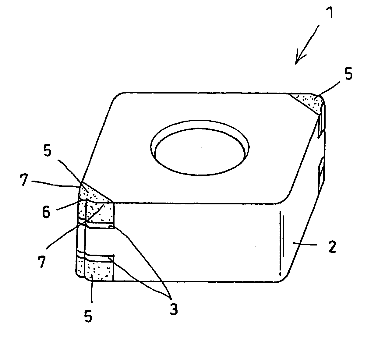
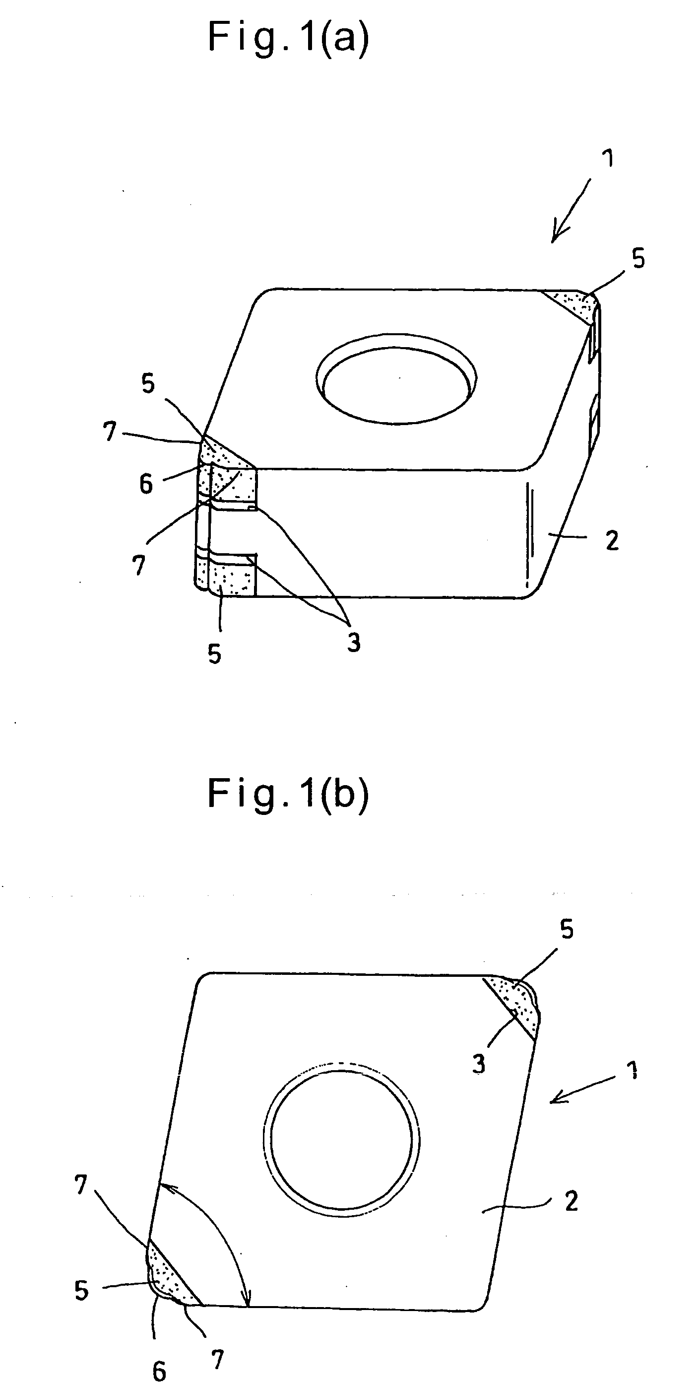
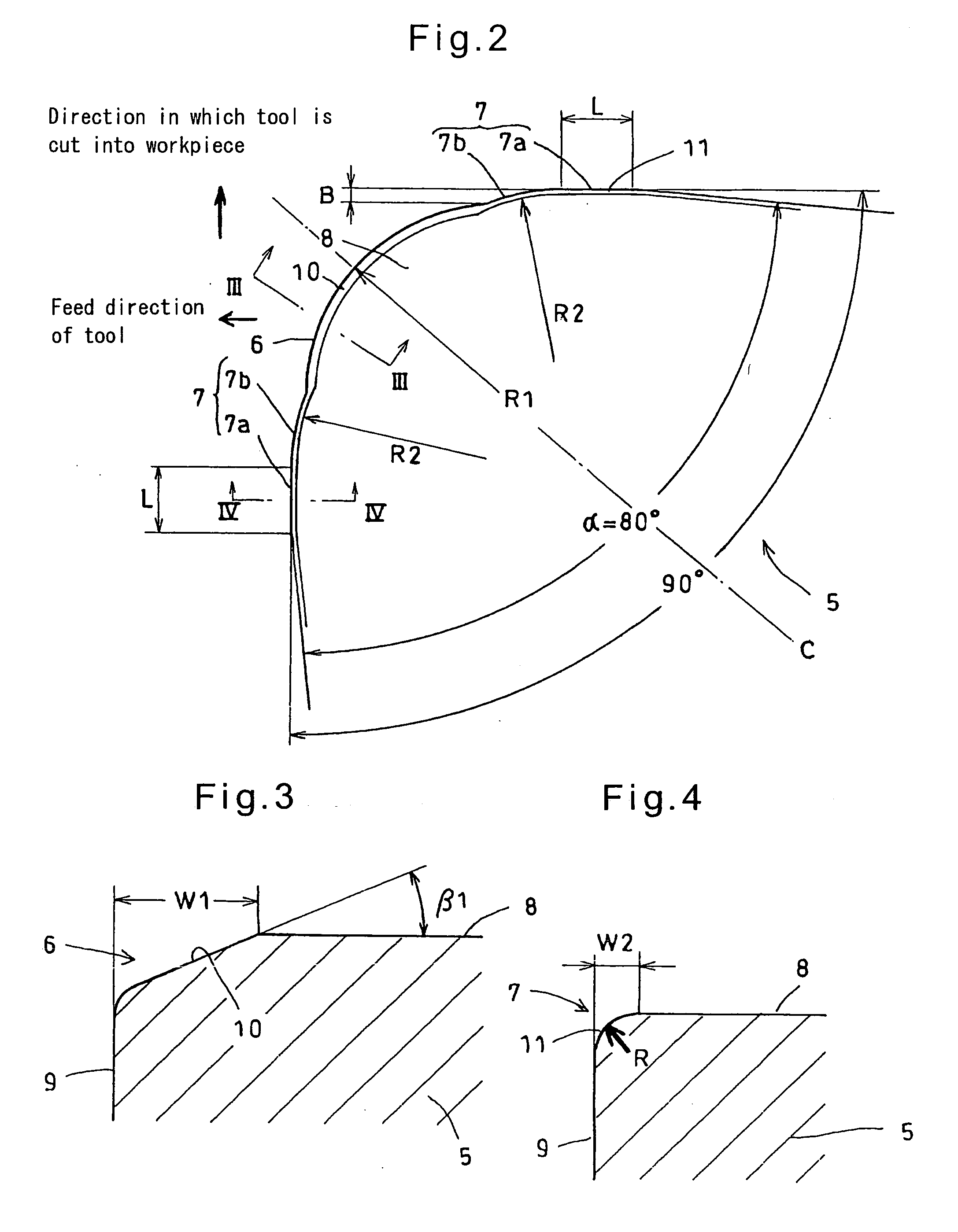
[0096]Cutting tool samples No. 51 to 69 shown in Table 2 were prepared. Any of the cutting tools used in EXAMPLE 2 comprised a substrate made of cemented carbide, and cBN-based sintered members each having a thickness of 1.8 mm, a nose angle α of 800 and a bottom length of 4 mm, including a carbide backing made of cemented carbide and brazed to one of the corners of the substrate. The cBN-based sintered members are inserts each classified into CNMA120408, CNMA120412 or CNMA120416 under ISO and having a cutting edge comprising a finishing cutting edge forming an arcuate nose, and superfinishing cutting edges which characterize the present invention. The cBN-based sintered members were of the same composition as those used in EXAMPLE 1.

[0097]The finishing cutting edge of any sample had a chamfer angle of 25° and a chamfer width of 0.13 mm (the border between the chamfer and the flank being rounded with a radius of curvature of 0.01 mm). The chamfers of the superfinishing cutting edges...


PUM

PropertyMeasurementUnit
Lengthaaaaaaaaaa
Lengthaaaaaaaaaa
Lengthaaaaaaaaaa

Abstract

It is an object to provide a cutting tool which can perform high-quality, high-efficiency machining of a workpiece such as hardened steel.
The cutting tool includes a finishing cutting edge 6 which initially cuts into the workpiece, and superfinishing cutting edges 7 for finishing the workpiece cut by the finishing cutting edge. The superfinishing cutting edges 7 project from the finishing cutting edge by a predetermined amount B in such a direction that the depth of cut of the superfinishing cutting edges increases. Each superfinishing cutting edge includes a burnishing portion 7a having a predetermined width L in the feed direction of the tool, and a wiper portion 7b. The superfinishing cutting edges 7 burnish the finished surface formed by the finishing cutting edge, while removing a affected layer formed by the finishing cutting edge.

Description

TECHNICAL FIELD[0001]This invention relates to a cutting tool capable of performing high-quality, high-efficiency cutting of (metal) workpieces, and specifically a cutting tool which can particularly advantageously cut hardened steel, and a method of cutting workpieces using such a cutting tool.BACKGROUND ART[0002]Cutting tools capable of performing high-quality, high-efficiency cutting of workpieces are disclosed in the below-mentioned Patent documents 1 and 2.[0003]The cutting tool disclosed in Patent document 1 is used for machining hardened steel and includes a major cutting edge which performs a major portion of the necessary cutting, and a minor cutting edge connecting with the major cutting edge to remove a affected layer formed on the surface of the workpiece by the major cutting edge and simultaneously finish the surface to required dimensions.[0004]The cutting tool (indexable insert) disclosed in Patent document 2 includes a cutting edge for rough cutting and a cutting edg...

Claims


Application Information

Patent Timeline
IPC IPC(8): B26D1/12B26D3/00
CPCB23B27/145Y10T407/23B23B2200/0433B23B2200/201B23B2200/204B23B2200/208B23B2200/242B23B2200/245B23B2200/28B23B2220/24B23B2222/04B23B2226/125B23B2226/315B23B2240/08B23B2270/26Y10T407/1962Y10T82/10Y10T407/27B23B27/1622Y10T83/0591B23D35/002
Inventor KURODA, YOSHIHIROKUKINO, SATORUOKAMURA, KATSUMIFUKAYA, TOMOHIRO
Owner SUMITOMO ELECTRIC HARDMETAL CORP
Why Eureka
Try Eureka