Composite Laser Element and Laser Oscillator Employing It

a laser oscillator and composite technology, applied in the direction of active medium materials, crystal growth process, polycrystalline material growth, etc., can solve the problems of inability to produce perfect crystal orientation between yag single crystals and yag single crystals, difficult to form and inability to manufacture clad core type of composite laser elements. , to achieve the effect of improving the bonding state, reducing the cost of manufacturing, and high thermal conductivity

Inactive Publication Date: 2008-12-04
IKESUE AKIO
View PDF6 Cites 32 Cited by
  • Summary
  • Abstract
  • Description
  • Claims
  • Application Information

AI Technical Summary

Problems solved by technology
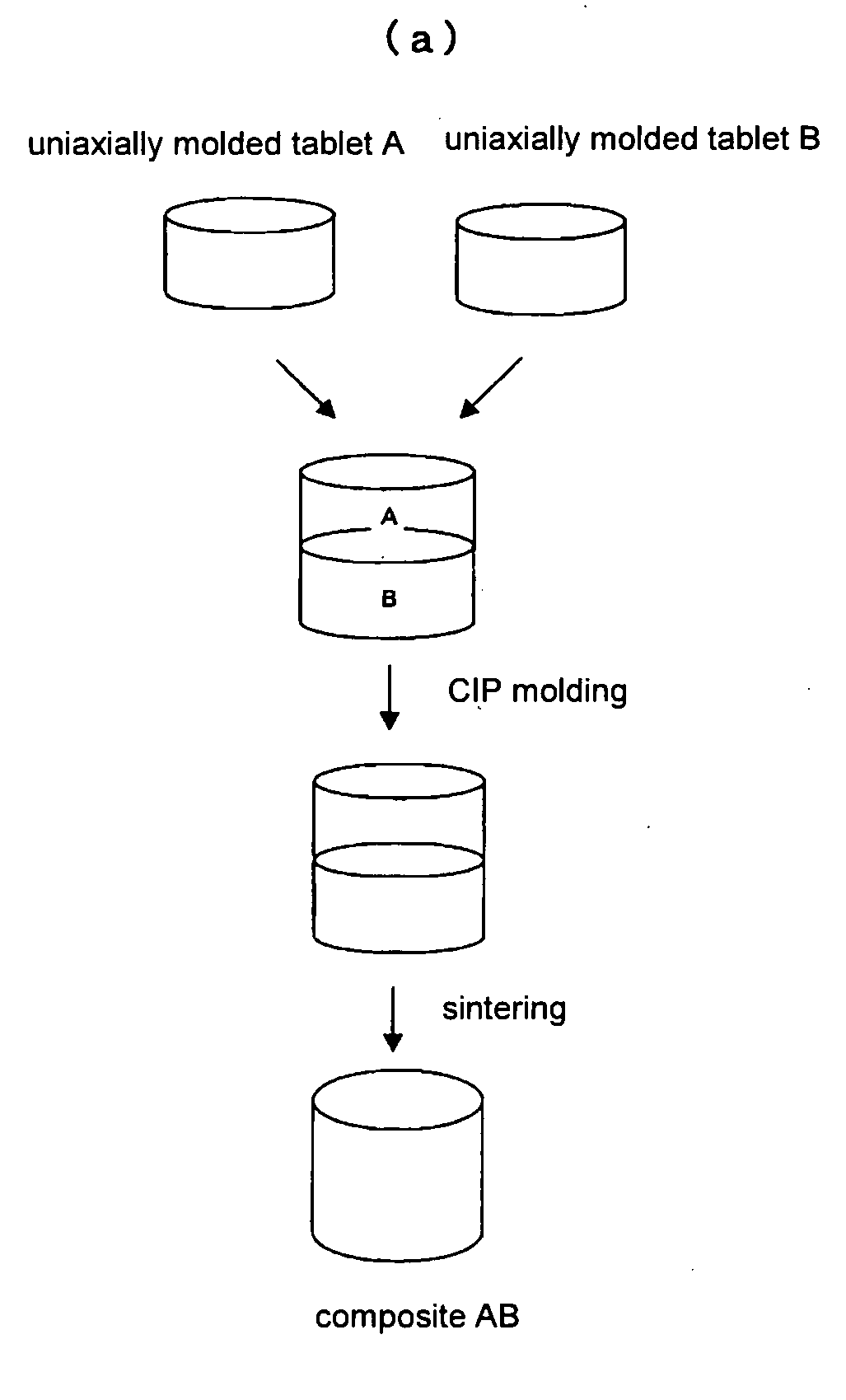
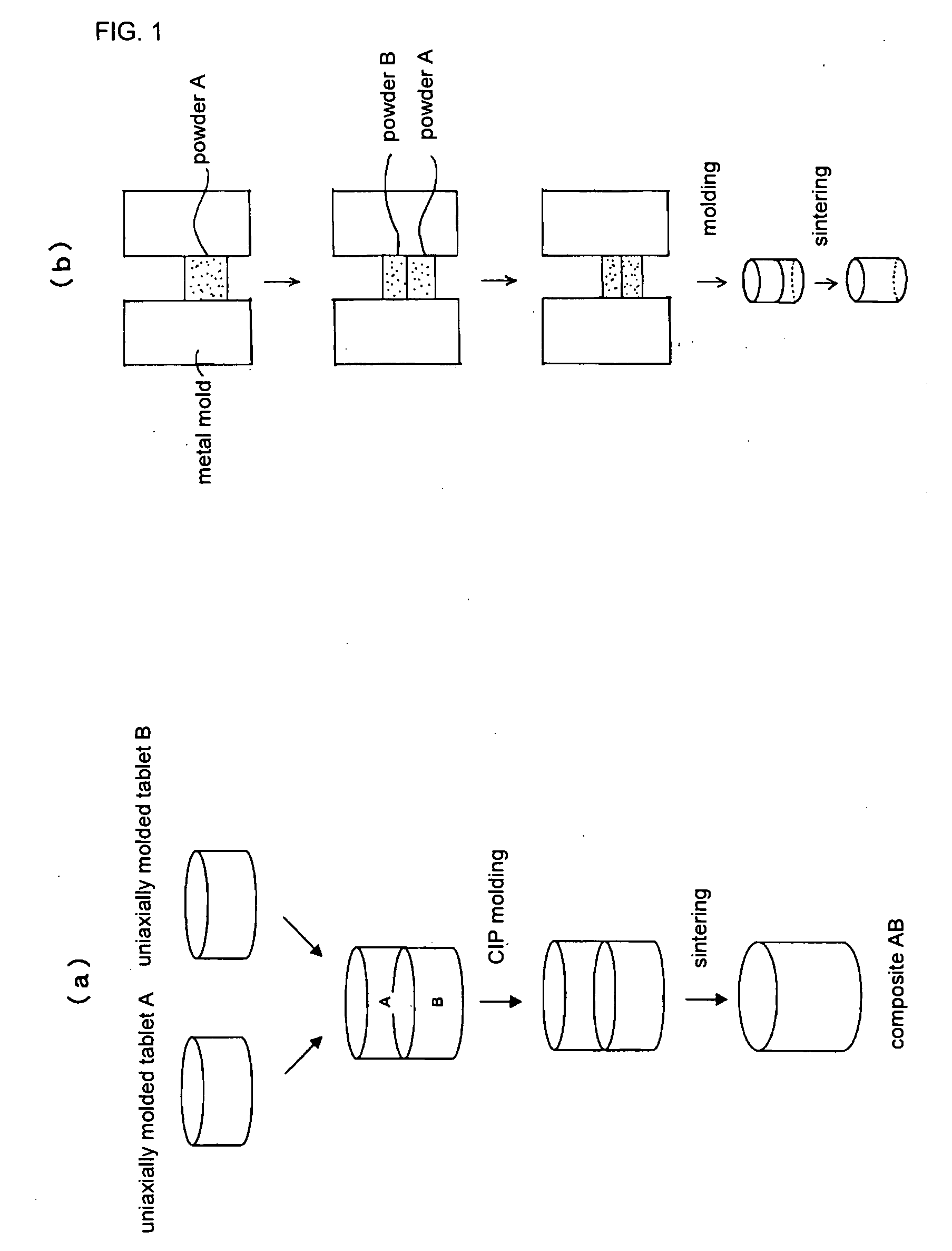
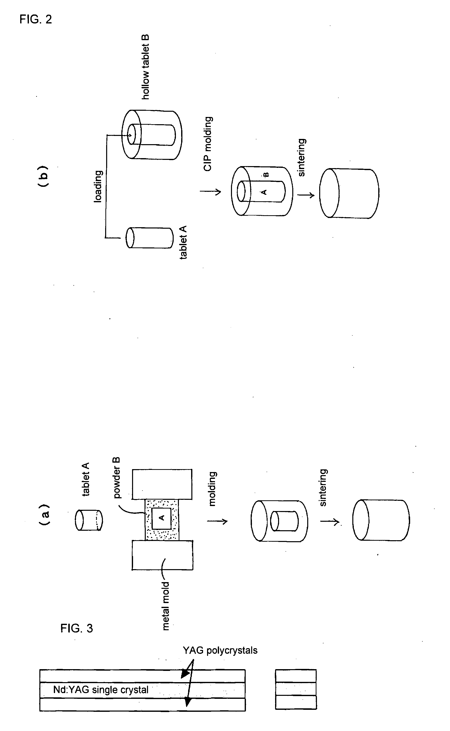
The above method, however, does not produce perfect matching in terms of crystal orientation between the Nd:YAG single crystals and YAG single crystals.
Even if the joining faces are polished to a high precision, they will still be far from an ideal smooth surface, so it is difficult to form joining faces that are satisfactory as optical materials in a subsequent joining treatment (such as a hot pressing step).
Furthermore, with hot pressing it is impossible to manufacture a clad core type of composite laser element in which a YAG single crystal is joined to the peripheral portion of a cylindrical Nd:YAG single crystal, and particularly such an element having a structure in which the curved faces are joined.
Furthermore, standard hot pressing involves uniaxial pressing in which a relatively high pressure is applied, and strain remains in the sample after treatment, so there are critical defects in the optical characteristics of the material that is obtained.
In case of a bonded material such as the above, however, light scattering is observed at the bonding interfaces when the interfaces are irradiated with a He—Ne laser, and in a destructive test in which a mechanical impact is applied to the bonding, a large portion of the fractured face is fractured via a smooth face (the polished face prior to joining).
It can be concluded from this situation as well that the above-mentioned technique does not adequately bond the single crystals together.
There are also cases in which beam quality decreases or there is a dramatic drop in the service life of the element, or when the laser element is broken near the bonding face.
Thermal energy generated inside the medium is transmitted to the outside by lattice vibration of the crystals, but because bonding is inadequate with a composite laser element produced by prior art, the lattice vibration does not transmit the energy well enough, so heat builds up at this point.
As a result, the element deteriorates in stages at the joint in the case of weak excitation, and impact damage occurs in the case of strong excitation, and in both cases it is difficult to maintain the intended function of the composite element.
However, the above technique has a number of problems because the bonding method itself is premised on the same bonding method as a technique such as hot pressing for bonding single crystals.
Specifically, these problems include 1) strain is produced in the interior of the one or more types of polycrystalline transparent ceramic that are bonded, 2) chipping on the side faces or internal cracking occurs, and 3) bonding face misalignment occurs between the materials during pressing.
Consequently, it is difficult to obtain a good bonding state, and in this respect it is difficult to obtain a polycrystalline composite laser medium that is high in optical quality.

Method used


Image

  • Composite Laser Element and Laser Oscillator Employing It
  • Composite Laser Element and Laser Oscillator Employing It
  • Composite Laser Element and Laser Oscillator Employing It

Examples


examples

[0166]Examples and comparative example will now be given to further clarify the features of the present invention, but the scope of the present invention is not limited to or by these examples.

examples 1 to 9

[0167]Composite laser elements having the structure shown in FIG. 5 were produced. The specific structure is shown in Table 1.

[0168]The clad core structure was such that the inner peripheral face of the core and the outer peripheral face of the clad were given a mirror finish in the machining of the core and clad, and the clearance between the two was adjusted to about 50 μm. When the clad was platinum, though, the outer peripheral face of the core was not mirror-polished, and was roughened to about #200.

[0169]The core was put into the clad, this assembly was put into a platinum or molybdenum capsule, and the material were joined by HIP at a temperature of 400 to 1600° C. and a pressure of 100 to 2000 kg / cm2. After this HIP treatment, the product was heat treated as necessary to increase the bonding strength. Both end faces of the composite laser element thus obtained were optically polished, and 1) the output characteristics when the laser was oscillated (threshold value (W) / slope ...

example 12

[0184]A super-high-output pulse laser oscillator was produced using the composite laser element obtained in Example 11.

[0185]As shown in FIG. 12, when a small switched laser oscillator featuring the composite laser element of Nd:YAG polycrystal and Cr4+:YAG single crystal of Example 11 was amplified with a commercially available regenerative amplifier, the laser was amplified up to a pulse width of 20 nsec and an output of 500 mJ.

[0186]Furthermore, as shown in FIG. 12, to this was added an amplifier (excited by semiconductor laser) in which a composite disk laser element, comprising a 1 mm YAG polycrystal (this may be a single crystal if the oscillation medium is a polycrystal) disposed on both sides of a Nd:YAG single crystal (or Nd:YAG polycrystal) with a diameter of 30 mm and a thickness of 4 mm or a 1.5 at % Nd:YAG polycrystal with a diameter of 30 mm and a thickness of 5 mm, was set up to Brewster's angle, which increased by output to 6 J. A super-high-output (6 J) having a sin...


PUM

PropertyMeasurementUnit
temperatureaaaaaaaaaa
surface roughness Raaaaaaaaaaa
pressureaaaaaaaaaa

Abstract

The present invention provides a composite laser element that solves the problems encountered with a conventional laser medium composed of an Nd:YAG single crystal or polycrystal, and exhibits excellent performance as a laser medium. The invention relates to a laser element in which two or more crystal materials are joined, wherein (1) at least one of the crystal materials is a transparent crystal material capable of laser oscillation, including a laser active element in a matrix crystal, and (2) the transparent crystal material capable of laser oscillation and / or a second crystal body joined thereto is a polycrystal.

Description

FIELD OF THE INVENTION[0001]This invention relates to a composite laser element and to a laser oscillator comprising this element.[0002]More particularly, the invention relates to a composite laser element in which a single crystal of Nd:YAG (this refers to YAG to which neodymium has been added, expressed by the general formula NdxY3-xAl5O12 (where x is the ratio in which neodymium substitutes for yttrium in a garnet structure); the same applies hereinafter), which is used as a laser oscillation element, or an Nd:YAG polycrystal or other such laser material that has been reported by the inventor and the others in recent years (see A. Ikesuke et al., Journal of American Ceramics Society, 78 (4), 1033 to 40, 1995), is bonded with the same or a different type of single crystal or polycrystal, and also relates to a laser oscillator using this composite laser element as a laser medium.BACKGROUND OF THE INVENTION[0003]Solid state lasers are widely used for marking, for cutting and welding...

Claims


Application Information

Patent Timeline
Patent Type & Authority Applications(United States)
IPC IPC(8): H01S3/16B32B37/04H01S3/042H01S3/06H01S3/0941
CPCC30B1/12C30B29/28H01S3/0604H01S3/061H01S3/0612H01S3/0625H01S3/07H01S3/09415H01S3/1062H01S3/113H01S3/1611H01S3/1643H01S3/1685H01S3/2316H01S2301/02
Inventor IKESUE, AKIO
Owner IKESUE AKIO
Why Eureka
Try Eureka