Double patterning with a double layer cap on carbonaceous hardmask

a carbonaceous hardmask and double layer technology, applied in the field of patterning, can solve the problems of slow progress on these fronts, hindered by substantial development and re-tooling and achieve greater manufacturing flexibility, enhance chemical vapor deposition, and reduce the half-pitch of features

Inactive Publication Date: 2008-12-04
APPLIED MATERIALS INC
View PDF5 Cites 29 Cited by
  • Summary
  • Abstract
  • Description
  • Claims
  • Application Information

AI Technical Summary

Benefits of technology

[0012]The carbonaceous mask layer provides a mechanically stable mask material capable of delineating features with sub-minimum CD and sub-minimum half-pitch. In one embodiment, the carbonaceous mask layer is resistant to subsequent processing at high temperature, e.g. greater than approximately 250° C. The resistance to higher deposition temperature provides flexibility in tuning characteristics of the cap layer important to DPL, such as, but not limited to deposition rate, etch rate, and optical transparency. The higher deposition temperature also provides greater manufacturing flexibility. In one such embodiment, the carbonaceous mask layer is formed by a chemical vapor deposition (CVD), which may be thermal process or a plasma enhanced process, i.e. plasma enhance chemical vapor deposition (PECVD).
[0013]In an embodiment, the carbonaceous mask layer, the first cap layer and the second cap layer are all formed by chemical vapor deposition (CVD) to reduce process complexity, cycle time and costs. In a further embodiment, where both the first cap layer and the second cap layer are formed with a silane (SiH4) precursor, to reduce manufacturing complexity, a single deposition chamber is employed to form the two cap layers successively. In one such embodiment employing CVD carbon, the carbonaceous mask layer, the first cap layer and second cap layer are successively formed within a single cluster tool system.
[0014]In an embodiment, the multi-layered mask has adequate transmission to enable alignment of the double patterned layer to previously formed features in the substrate. In a further embodiment, the first cap layer is selected from a material having high transparency in the visible wavelengths used for alignment. A material providing contrast to the first cap layer in visible wavelengths is selected for the second cap layer to enable alignment of the second lithographically defined pattern to the first lithographically defined pattern. The thicknesses of the first and second cap layer are further selected to provide sufficient etch selectivity to each other as well as the carbonaceous mask layer to serve as etch stops and / or etch masks while introducing minimal topography. In one such embodiment, the first cap layer is silicon dioxide and the second cap layer is amorphous silicon. In a particular embodiment, both the first and second cap layers have a thickness between 100 Å and 600 Å.

Problems solved by technology

However, this reduction in feature CD comes at the expense of an increased spacing between features, as depicted by spacing ‘y’ in FIG. 1C.
Progress on these fronts, however, has been slow, hindered by the substantial development and re-tooling required.
DPL however is potentially cost prohibitive, particularly as a result of production cycle time, which increases when a DPL integration scheme employs many additional operations to pattern a particular layer.
Production cycle time increases are particularly troublesome for product lines which experience significant price erosion over a time period that is only a small multiple of the production cycle time.

Method used


Image

  • Double patterning with a double layer cap on carbonaceous hardmask
  • Double patterning with a double layer cap on carbonaceous hardmask
  • Double patterning with a double layer cap on carbonaceous hardmask

Examples


Embodiment Construction

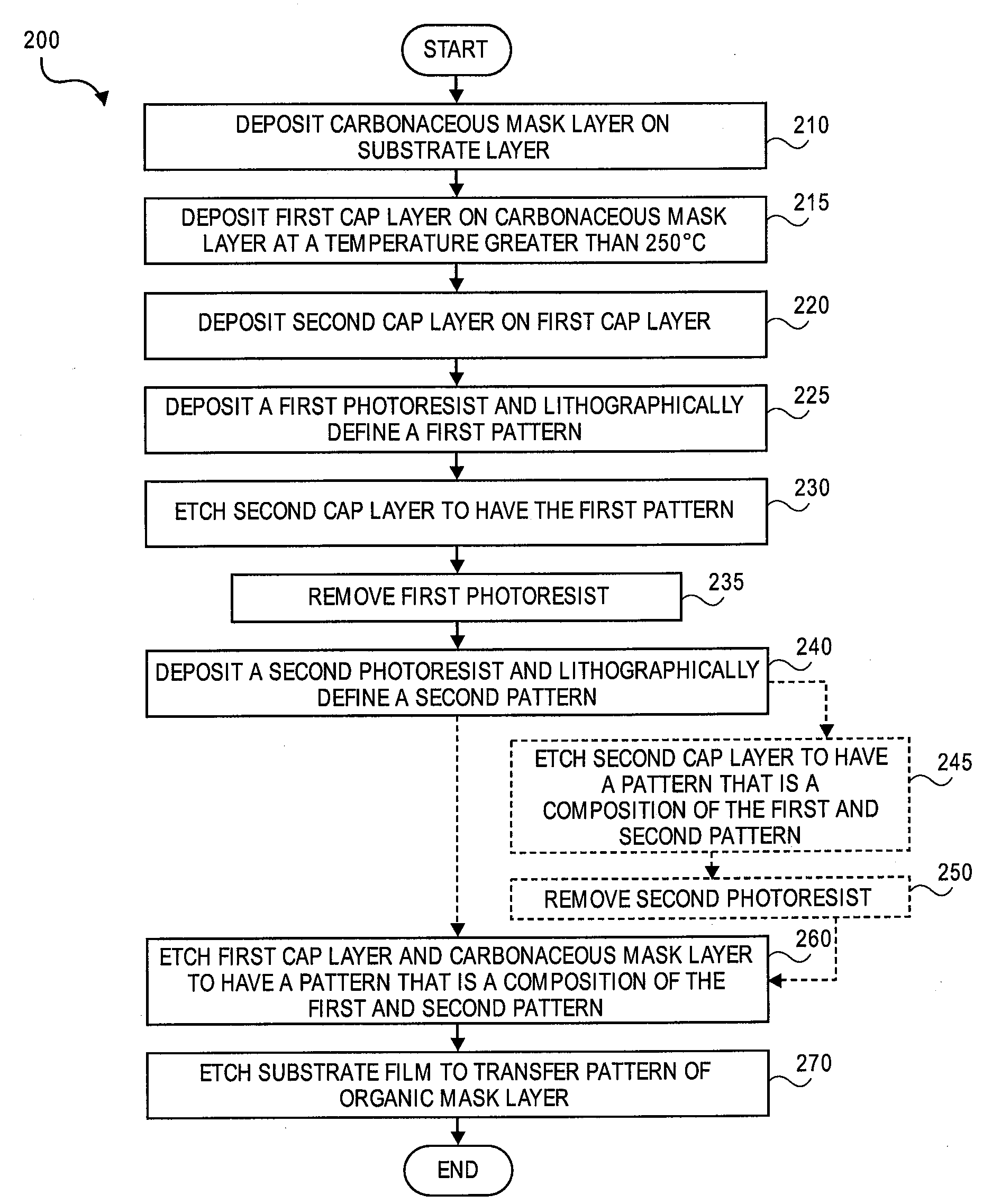
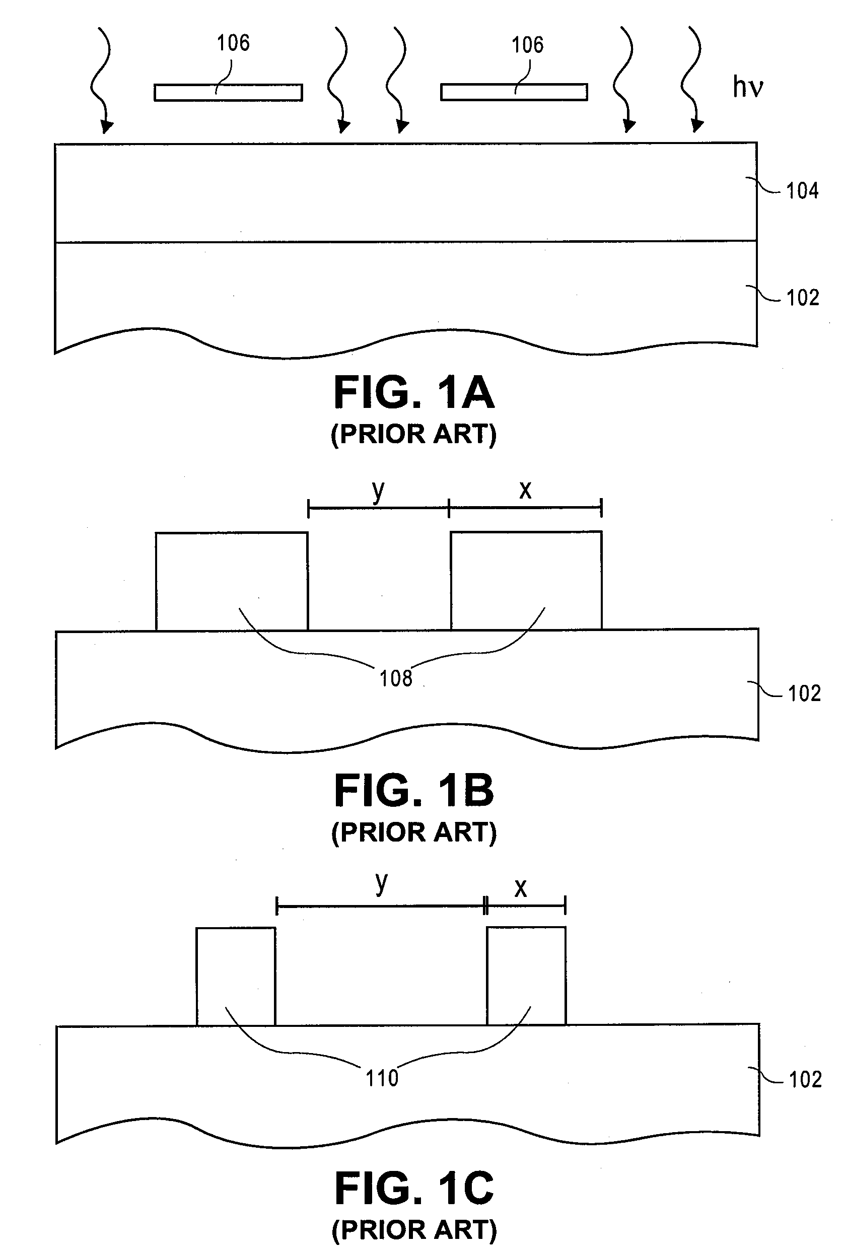
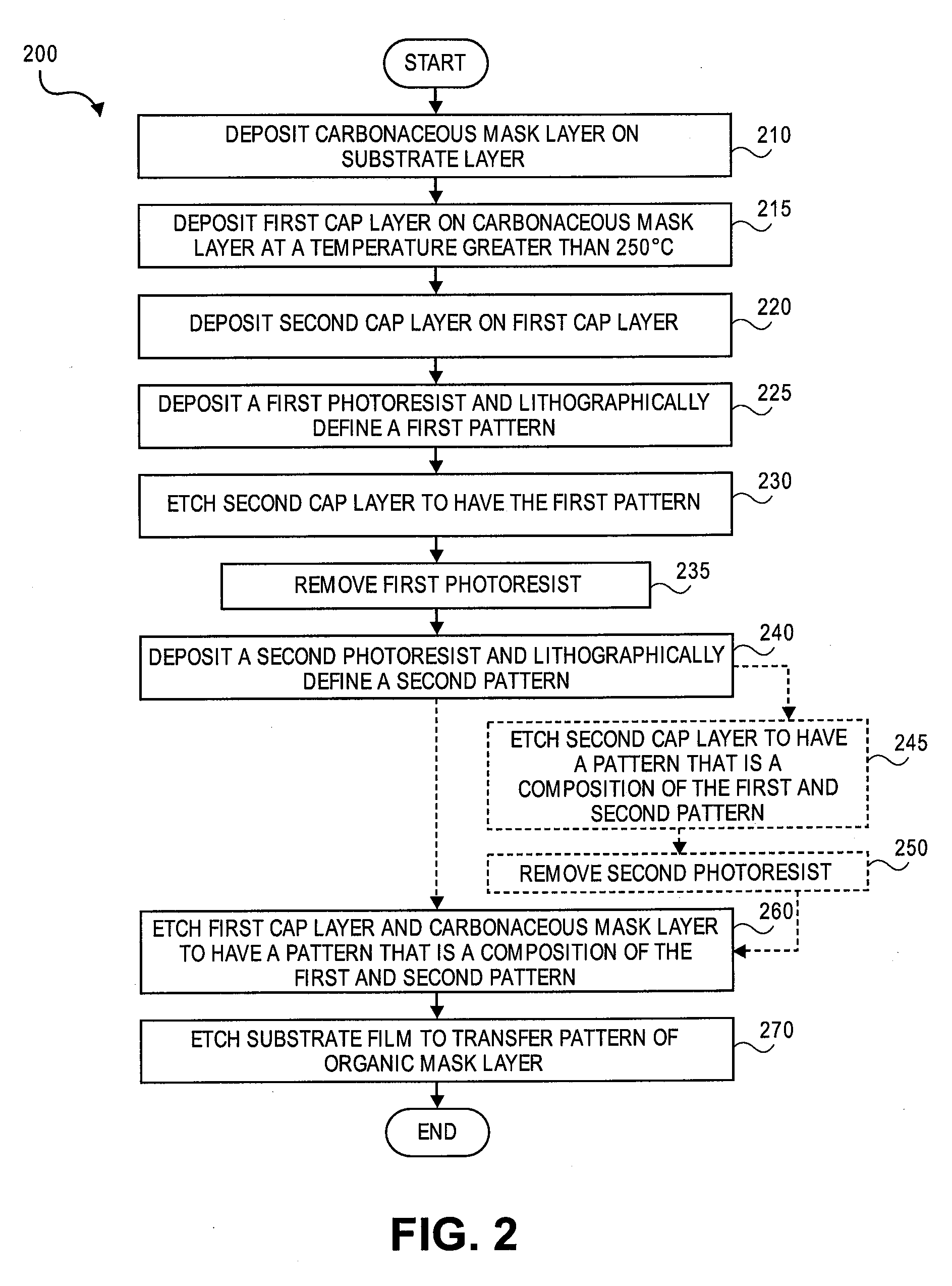
[0023]Embodiments of double patterning methods are described herein with reference to figures. However, particular embodiments may be practiced without one or more of these specific details, or in combination with other known methods, materials, and apparatuses. In the following description, numerous specific details are set forth, such as specific materials, dimensions and processes parameters etc. to provide a thorough understanding of the present invention. In other instances, well-known semiconductor processes and manufacturing techniques have not been described in particular detail to avoid unnecessarily obscuring the present invention. Reference throughout this specification to “an embodiment” means that a particular feature, structure, material, or characteristic described in connection with the embodiment is included in at least one embodiment of the invention. Thus, the appearances of the phrase “in an embodiment” in various places throughout this specification are not nece...


PUM

PropertyMeasurementUnit
temperatureaaaaaaaaaa
temperaturesaaaaaaaaaa

Abstract

Methods to etch features in a substrate with a multi-layered double patterning mask. The multi-layered double patterning mask includes a carbonaceous mask layer, a first cap layer on the carbonaceous mask layer and a second cap layer on the first cap layer. After forming the multi-layered mask, a first lithographically defined pattern is etched into the second cap layer. A double pattern that is a composition of the first lithographically defined pattern etched in the second cap layer and a second lithographically defined pattern is then etched into the first cap layer and the carbonaceous mask layer. The double pattern formed in the carbonaceous mask layer is then transferred to a substrate layer and any portion of the multi-layered mask remaining is then removed.

Description

CROSS REFERENCE TO RELATED APPLICATIONS[0001]This application claims the benefit of U.S. Provisional Application No. 60 / 932,859, filed Jun. 1, 2007, which is hereby incorporated by reference.BACKGROUND[0002]1. Field[0003]Embodiments of the present invention relate to the electronics manufacturing industry and more particularly to a patterning process enabling a reduced half pitch.[0004]2. Discussion of Related Art[0005]Lithography is used in the manufacture of integrated circuits (ICs). FIGS. 1A-C illustrate cross-sectional views of a conventional semiconductor lithographic process. Referring to FIG. 1A, a photoresist layer 104 is provided above a semiconductor stack 102. A mask or reticle 106 is positioned above photoresist layer 104. A lithographic process includes exposure of photoresist layer 104 to radiation (hv) having a particular wavelength (λ), as indicated by the arrows in FIG. 1A. Referring to FIG. 1B, photoresist layer 104 is subsequently developed to remove the portions...

Claims


Application Information

Patent Timeline
Patent Type & Authority Applications(United States)
IPC IPC(8): G03C5/00
CPCH01L21/0337H01L21/0338
Inventor BENCHER, CHRISTOPHER D.DAI, HUIXIONG
Owner APPLIED MATERIALS INC
Why Eureka
Try Eureka