Ultrasonic endoscope and ultrasonic endoscopic apparatus

a technology of ultrasonic endoscope and endoscope, which is applied in the field of ultrasonic endoscope and ultrasonic endoscope, can solve the problems of increasing the temperature affecting the operation of the ultrasonic endoscope, and unable to achieve sufficient heat dissipation effect, etc., and achieves the effect of small size and slight temperature rise of the insertion par

Inactive Publication Date: 2008-12-04
FUJIFILM CORP
View PDF6 Cites 16 Cited by
  • Summary
  • Abstract
  • Description
  • Claims
  • Application Information

AI Technical Summary

Benefits of technology

[0018]According to the present invention, since the heat-conducting member is provided inside of the covering material that covers the insertion part of the ultrasonic endoscope, an ultrasonic endoscope...

Problems solved by technology

In this regard, not the entire energy of the drive signals is converted into acoustic energy but a significant proportion of the energy becomes heat, and there has been a problem that the temperature rises in use of the ultrasonic endoscope.
However, a small-diameter endoscope such as a bronchial endoscope having an outer diameter of φ6.9 mm or less has no space for such a heat absorbing part including a refrigerant feeder and a refrigerant pipe.
However, the signal cable of the endoscope has a small sectional area, and, if the signal cable is used for heat dissipation, no sufficient heat dissipation effect is obtained due to the small sectional area.
Specifically, in body cavity examination of upper digestive organs, bronchial tube, and so on, a small-diameter endoscope having an outer diameter of φ6.9 mm is used, and downsizing of the ultrasonic endoscope becomes a challenge in view of reduction in physical stress on patients.
However, as the transmission output of ultrasonic waves is i...

Method used


Image

  • Ultrasonic endoscope and ultrasonic endoscopic apparatus
  • Ultrasonic endoscope and ultrasonic endoscopic apparatus
  • Ultrasonic endoscope and ultrasonic endoscopic apparatus

Examples


second embodiment

[0047]Next, the present invention will be explained.

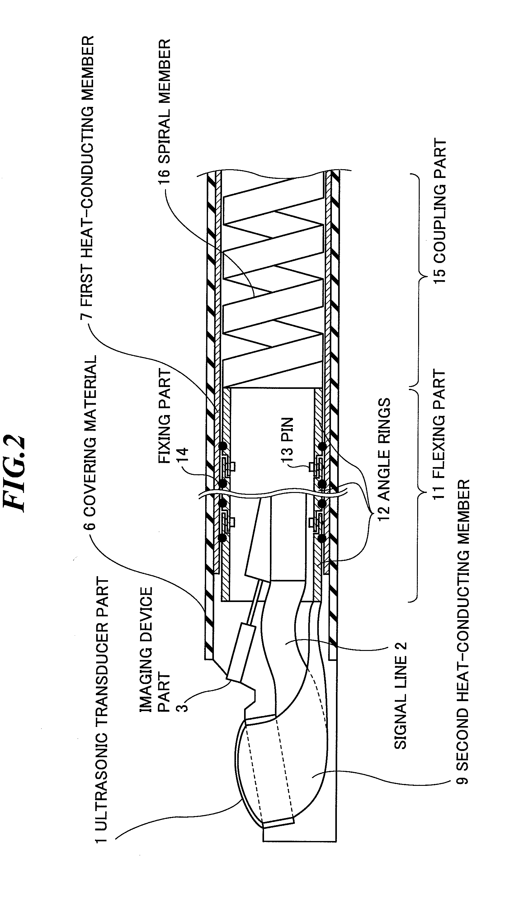
[0048]FIG. 5 schematically shows a leading end of an insertion part of an ultrasonic endoscope according to the second embodiment of the present invention. In the second embodiment of the present invention, the plural angle rings 12 of the flexing part 11 are connected by using the pins 13 as is the case of the first embodiment of the present invention, but sufficient heat release is hardly achieved through the connection by the pins 13. On this account, heat is released from the plural angle rings 12 to the first heat-conducting member 7 via the fixing parts 14 and a flexing part heat-conducting member 21 is provided for promotion of heat transfer among the angle rings 12.

[0049]The flexing part heat-conducting member 21 has flexibility and high conductivity, and formed in a foil, wire, mesh, or sheet shape by employing a material containing metal and / or graphite. Preferably, the metal material contains copper or copper alloy with ...

third embodiment

[0050]Next, the present invention will be explained.

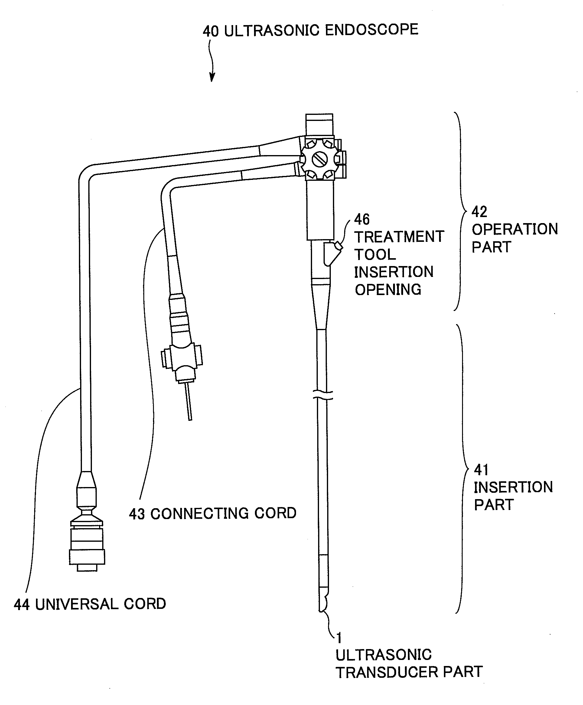
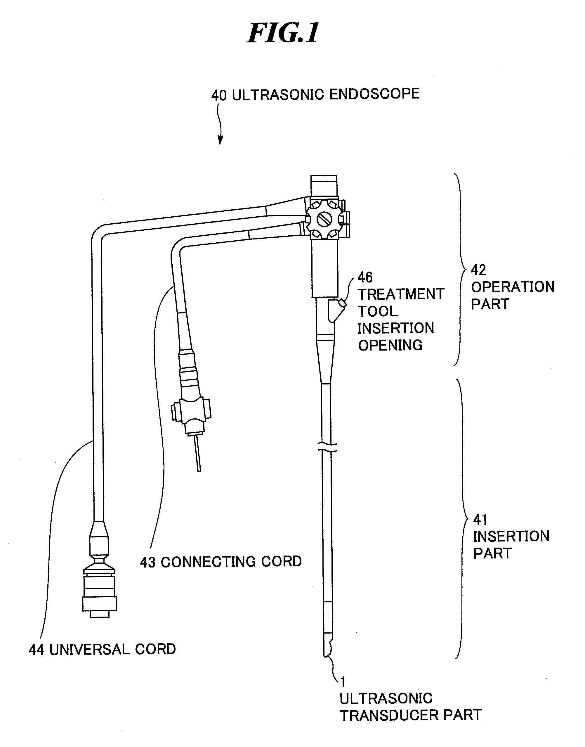
[0051]FIG. 6 schematically shows a leading end of an insertion part of an ultrasonic endoscope according to the third embodiment of the present invention. In the third embodiment of the present invention, the outer diameter of a portion from the ultrasonic transducer part 1 to the flexing part 11 is made smaller than the outer diameter of a portion from the coupling part 15, which is nearer the operation part 42 (FIG. 1) side than the flexing part 11, to the operation part 42. Here, the flexing part 11 is not gradually thin but uniformly thin, and thus, its insertability into thin bronchial tubes is good. Further, the sectional area of the first heat-conducting member 7 at the coupling part 15 is made larger than the sectional area of the first heat-conducting member 7 at the flexing part 11. Thereby, heat radiation of the coupling part 15, which becomes insufficient when the ultrasonic transducers are stacked for increasing the tr...

fourth embodiment

[0052]Next, the present invention will be explained.

[0053]FIG. 7 schematically shows a leading end of an insertion part of an ultrasonic endoscope according to the fourth embodiment of the present invention. In the fourth embodiment of the present invention, the flexing part heat-conducting member 21, which has been explained in the second embodiment of the present invention, is added to the third embodiment of the present invention. According to the fourth embodiment, since heat is transferred among the plural rings 12 via the flexing part heat-conducting member 21, the heat is released to the first heat-conducting member 7 more efficiently than in the case of the third embodiment.


PUM


Abstract

An ultrasonic endoscope having a small size and a slight temperature rise of an insertion part even when the transmission output of an ultrasonic transducer part is increased or an imaging device is attached thereto. The ultrasonic endoscope includes: an ultrasonic transducer part having plural ultrasonic transducers for transmitting and receiving ultrasonic waves; a flexing part for flexibly supporting the ultrasonic transducer part; a coupling part for coupling the flexing part to an operation part; a covering material for covering at least the flexing part and the coupling part; and a heat-conducting member provided inside of the covering material and coupled to the ultrasonic transducer part, for transferring heat generated in the ultrasonic transducer part to the operation part.

Description

BACKGROUND OF THE INVENTION[0001]1. Field of the Invention[0002]The present invention relates to an ultrasonic endoscope to be used for body cavity examination of upper digestive organs, bronchial tube, and so on, and the present invention further relates to an ultrasonic endoscopic apparatus including the ultrasonic endoscope.[0003]2. Description of a Related Art[0004]In medical fields, various imaging technologies have been developed in order to observe the interior of an object to be inspected and make diagnoses. Among them, especially, ultrasonic imaging for acquiring interior information of the object by transmitting and receiving ultrasonic waves enables image observation in real time and provides no exposure to radiation unlike other medical image technologies such as X-ray photography or RI (radio isotope) scintillation camera. Accordingly, ultrasonic imaging is utilized as an imaging technology at a high level of safety in a wide range of departments including not only the ...

Claims


Application Information

Patent Timeline
IPC IPC(8): A61B8/12
CPCA61B8/12A61B8/445A61B8/546
Inventor NAGANO, KAZUHIKOHYUGA, HIROAKI
Owner FUJIFILM CORP
Why Eureka
Try Eureka