Method for improving synchronization and information transmission in a communication system

a communication system and information transmission technology, applied in the field of radio communication system, can solve the problems of insufficient peak detection of differential correlation in a frame of received samples, very sensitive timing acquisition to noise/interference, and complicate the implementation of signal generator and demodulator, so as to reduce noise/interference sensitivity

Active Publication Date: 2008-12-18
HUAWEI TECH CO LTD
View PDF13 Cites 19 Cited by
  • Summary
  • Abstract
  • Description
  • Claims
  • Application Information

AI Technical Summary

Benefits of technology

[0034]The invention significantly improves the performances of the timing acquisition in the receiver in applications where the synchronization signals transmitted to support and alleviate the timing acquisition in the receiver should also carry some information, such as transmitter's identification number, etc. One of such applications is cell search procedure in a cellular system. Besides, it allows an increased amount of information to be carried by the synchronization signals, compared to Document 1.

Problems solved by technology

Although the above solution for the synchronization channel seems quite promising in terms of reduced overall cell search time, still its timing acquisition is very sensitive to noise / interference due to the broad triangular shape of the differential correlation function.
Consequently, the peak detection of the differential correlation in a frame of received samples is not enough, because it can not discriminate the peaks coming from the different cells.
Further on, the complex conjugation of the basic repeated waveform in the second half of the signal might complicate the implementation of the signal generator and demodulator, especially if the signal is supposed to be obtained by the IDFT of a complex pseudo-noise sequence.

Method used


Image

  • Method for improving synchronization and  information transmission in a communication  system
  • Method for improving synchronization and  information transmission in a communication  system
  • Method for improving synchronization and  information transmission in a communication  system

Examples


embodiment 1

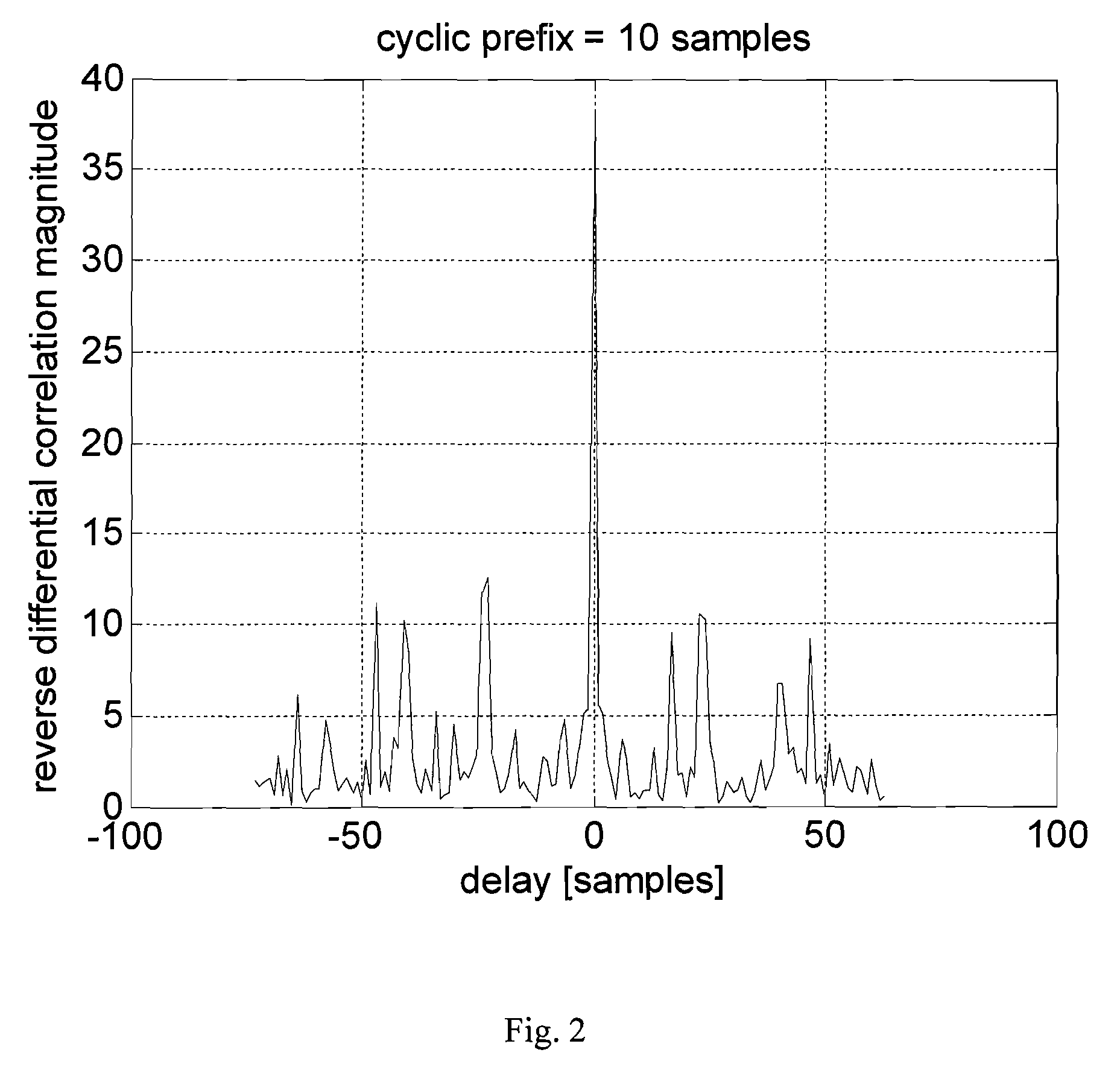
[0051]To illustrate the design of centrally symmetric synchronization signals (6) and the properties of the corresponding reverse differential correlation functions (5), we generate the set of OFDM centrally symmetric synchronization signals starting from the assumptions given in Document 1: the sampling frequency is 1.92 MHz, the sub-carrier spacing is 15 kHz, the maximum number of occupied sub-carriers is Nosc=76 out of totally N=128 sub-carriers within 1.92 MHz frequency band (the transmission bandwidth is 1.25 MHz). The occupied sub-carriers are modulated by the elements of a pseudo-random sequence from the set of sequences with good cross-correlation properties. The different sequences from the set are labelled by the different cell identification numbers (IDs). After the DFT demodulation of the received OFDM signal the transmitted sequence can be identified by de-mapping from the sub-carriers, followed by a certain signal processing. Low cross-correlation between sequences con...

embodiment 2

[0075]The timing acquisition performance results for the signals from Embodiment 1 has demonstrated that if the frequency error is above a certain threshold, the differential correlation produces better timing acquisition than the reverse differential correlation, while bellow a certain frequency error it is opposite.

[0076]This result suggests that if the frequency error during the initial cell search is above 2 ppm, it would be beneficial that the synchronization signal is both centrally symmetric and periodic. Such a signal could be detected in the UE both by the differential correlation and the reverse differential correlation, depending on UE's cell search mode, i.e. depending on the maximum expected frequency error in between the carrier frequency of received signal and the frequency of the reference RF signal in the receiver.

[0077]Thus, the initial cell search the synchronization signals transmitted from the base stations should be performed by using the differential correlati...

embodiment 3

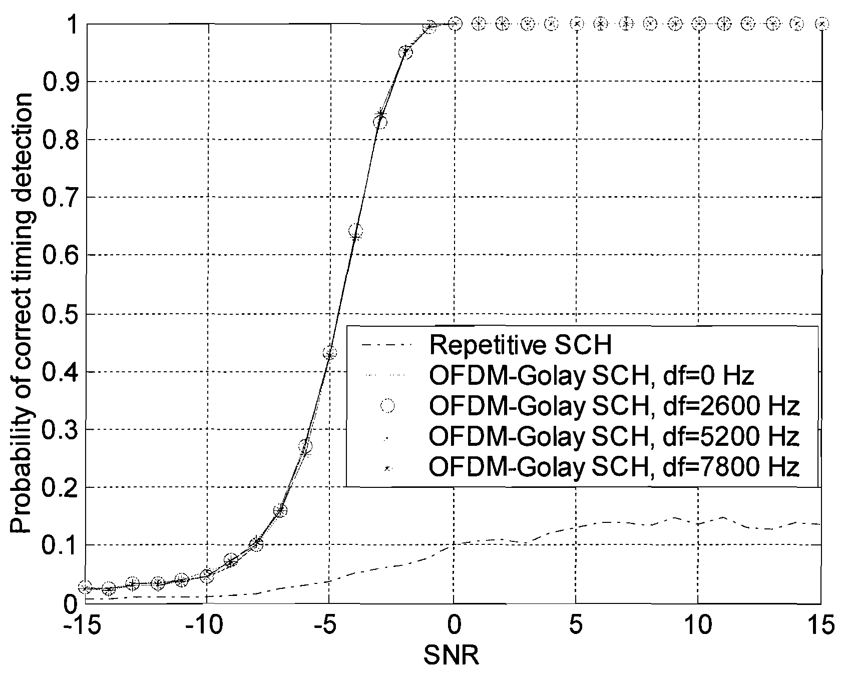
[0084]As mentioned above, the error tolerance zone in practice cannot be longer than a few samples. In that case, however, even the differential correlation (used to detect the repetitive synchronization signal from Document 1) shows rather bad performances at high frequency errors, as it can be seen in FIG. 5, where the timing acquisition performances of the signals from FIG. 3 are evaluated with the tolerance zone of 2 samples.

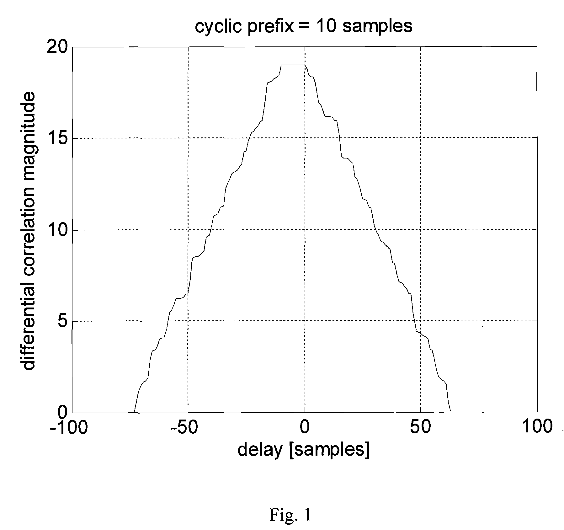
[0085]The reason for bad performances of the differential correlation lies in the plateau shown in FIG. 1, which makes it highly probable that the noise will produce a correlation peak at the delay within the correlation plateau less than the zero (correct) delay. Thus, the curve corresponding to repetitive signal converges very slowly to the value 1 with an increase of SNR.

[0086]The previous discussion about the different types of the ambiguity functions leads to consideration of other types of the pseudo-noise sequences, with ambiguity functions more toler...


PUM


Abstract

The present invention relates to a method for improving synchronization and information transmission in a communication system, including: generating a signal with a time symmetric property based on a uniquely identifiable sequence c(l) from a set of sequences, sending the signal over a communication channel, receiving the signal, calculating and storing a correlation, finding the delay that result in a maximum correlation magnitude, detecting the unique sequence c(l) from the set of sequences. The method is distinguished by: generating the signal with a centrally symmetric part, s(k), the centrally symmetric part s(k) being symmetric in the shape of the absolute value thereof, storing the reverse differential correlation D(p) from a block of N received signal samples r(k), k=0, 1, . . . , N−1. The present invention also relates to a transmitter unit and a receiver unit of a communication system, and a radio communication system.

Description

CROSS-REFERENCE TO RELATED APPLICATIONS[0001]This application is a Continuation of PCT / CN2006 / 000076 filed Jan. 18, 2006, which is incorporated by reference in its entirety herein. The PCT application published in English as WO 2007 / 082408.FIELD OF THE INVENTION[0002]The present invention relates to a method for synchronization and information transmission in a communication system, and more particularly to a radio communication system, a transmitter unit and a receiver unit.BACKGROUND OF THE INVENTION[0003]Several different proposals for the EUTRA synchronization channel (SCH), intended for use in the cell search procedure are proposed in 3rd Generation Partnership Project RAN1 until now. For instance: Motorola, “Cell Search and Initial Acquisition for OFDM Downlink”, R1-051329, Seoul, Korea, Nov.7-11, 2005 (this paper is called Document 1 hereinafter).[0004]Compared to the solution existing in the WCDMA standard, Motorola's proposal makes a step forward towards concurrent initial ...

Claims


Application Information

Patent Timeline
Patent Type & Authority Applications(United States)
IPC IPC(8): H04L7/00
CPCH04L7/041H04L7/043H04L27/2675H04L27/2613H04L27/2655H04L27/26132H04L5/0007
Inventor POPOVIC, BRANISLAV
Owner HUAWEI TECH CO LTD
Why Eureka
Try Eureka