[0006]Proceeding from the expounded disadvantages of the known prior art, therefore, the object on which the invention is based is to conceive a radial rolling bearing, in particular a grooved rolling bearing, which is designed with a bearing cage which can be produced simply and cost-effectively and, on the one hand, which ensures an axial guidance of the rolling bodies designed as spherical disks and, on the other hand, by means of which, even at low bearing rotational speeds and / or in the case of a mixed axial and radial bearing load, a contact generating frictional heat can be avoided between the spherical disks and the bearing cage.DESCRIPTION OF THE INVENTION
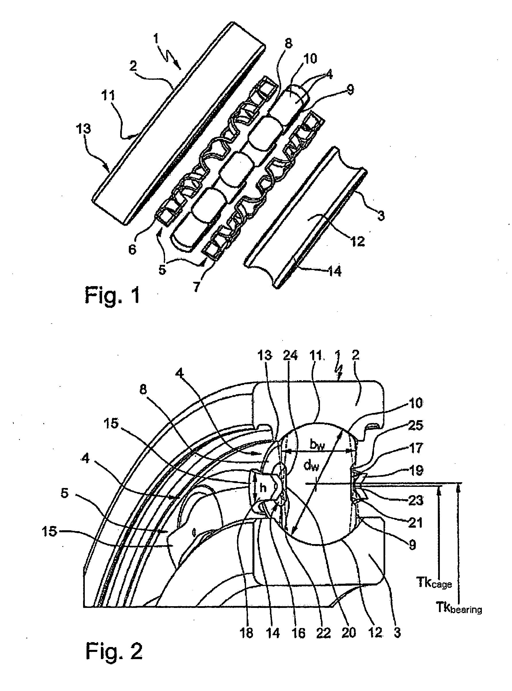
[0009]Thus, according to claim 2, in the radial rolling bearing according to the invention there is provision for the center region of the side faces of the rolling bodies to be formed either by centric depressions incorporated into these side faces or by concentric recesses incorporated into these side faces. If the rolling bodies are designed with centric depressions, these are preferably designed in the form of circular shallow troughs, whereas, if the rolling bodies are designed with concentric recesses, these are preferably formed by shallow annular grooves which run around the rolling
body axis. These depressions or recesses in this case have, above all, the
advantage that the
mass center of gravity of the rolling bodies is displaced radially outward toward their running surfaces and therefore the running properties of the rolling bodies are substantially improved.
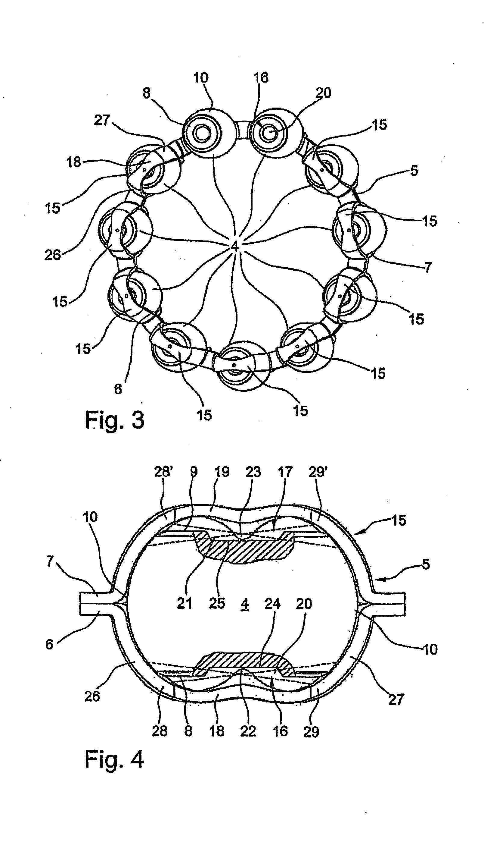
[0010]If the rolling bodies are designed in their side faces with centric depressions designed as circular troughs, then, as claimed in claim 3, a further feature of the radial rolling bearing designed according to the invention is that the point contacts provided for the axial guidance of the rolling bodies, between the center region of the side faces and the longitudinal webs of the cage pockets can be produced via two cone apices incorporated along the longitudinal center into the longitudinal webs. These cone apices projecting axially into the centric depressions in the side faces of the rolling bodies are operatively connected to the planar bottom of the depressions in the case of guidance, but, when the bearing is in operation, have no permanent contact with the bottom of the depressions. Furthermore, it has proved advantageous to design the cone apices to be rounded at their ends, in order to prevent a premature wear of these cone apices.
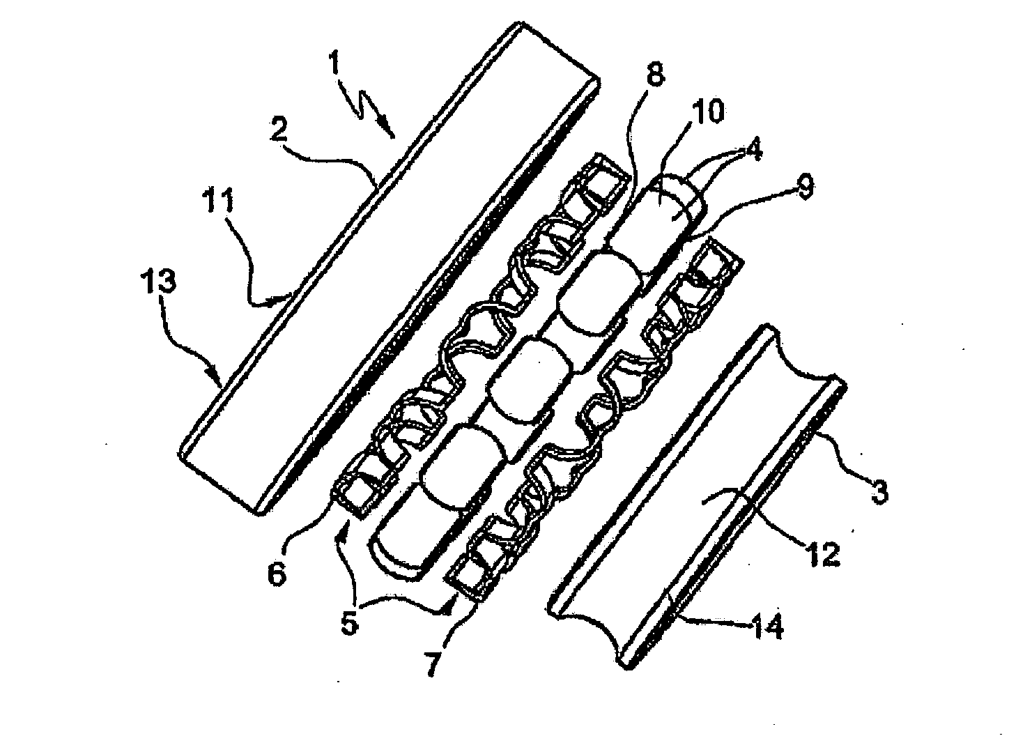
[0012]According to claims 5 to 7, furthermore, the radial rolling bearing designed according to the invention is also distinguished in that the transverse webs of the cage pockets, said transverse webs being designed to be curved according to the longitudinal and transverse radii of the running surfaces of the rolling bodies, extend beyond these running surfaces on both sides in such a way that the longitudinal webs of the cage pockets, said longitudinal webs being connected to the transverse webs between these via rounded transitional regions, are arranged at a distance from the side faces of the rolling bodies. The design of the transverse webs of the cage pockets in which the transverse webs extend beyond the running surfaces of the rolling bodies has in this case the effect that the rolling bodies have in the running direction, on both sides, a degree of freedom of an angle of about 3° to 7° which is limited by the transitional regions to the longitudinal webs of the cage pockets and by means of which, in the event of tilting movements of the rolling bodies occurring transversely with respect to the running direction below a permissible minimum rotational speed, a contact generating frictional heat is avoided between the spherical disks and the bearing cage. By contrast, the longitudinal webs of the cage pockets being arranged at a distance from the side faces has the
advantage that the rolling bodies at the same time have, on both sides, an axial degree of freedom of an angle of about 12° to 18° which is limited by the upper and lower edges of the longitudinal webs and by means of which the rolling bodies can orient themselves automatically with respect to the pressure angle of the radial bearing under radial and axial bearing load.
[0014]Finally, the features of the radial bearing designed according to the invention, as claimed in claims 9 and 10, also contribute to achieving the said object, according to which features the bearing cage either is formed as a stamped / drawn / embossed part, capable of being produced in a non-
cutting manner, from a
metal material or as an injection molding from an industrial or high-temperature plastic or alternatively is produced from a composite
fiber plastic consisting of a fabric reinforcement and
resin matrix. As regards the
metal materials, in this case, above all, steel,
brass or aluminum have proved to be suitable, by means of which the bearing cage can additionally be coated completely or to a limited extent at its contact points with the rolling bodies with functional
layers consisting of hard material, chrome iron,
oxide ceramics or
molybdenum or can be injection-molded around with an industrial plastic. By contrast, appropriate industrial plastics for the bearing cage are PA 66 or PA 46 with or without inlays of
glass fiber, while, for example, PAEK, PEEK, TPI or PAI with suitable additives or inlays of
glass fiber can be used as high-temperature plastics. Said materials have in this case proved to be particularly cost-effective in terms of their procurement and, furthermore, make it possible to use cost-effective manufacturing methods for the bearing cage, so that radial bearings designed with bearing cages of this type can, overall, be produced at low production costs.
[0015]The radial rolling bearing designed according to the invention thus has the
advantage, as compared with the radial rolling bearings known from the prior art, that, by the bearing cage being designed with cage pockets in which the rolling bodies are axially guided solely by two point contacts, it takes into account the kinematic conditions in such a radial bearing to an extent such that it has a first degree of freedom, by means of which the wobbling movements, occurring below a permissible minimum rotational speed, or tilting movements, occurring transversely with respect to the running direction, of the rolling bodies no longer lead to a contact of the rolling bodies with the bearing cage and therefore no longer to frictional heat or to an inadmissible rise in the
operating temperature of the radial rolling bearing. At the same time, by virtue of their
point contact guidance in the cage pockets, the rolling bodies have a sufficient second degree of freedom in the axial direction, by means of which they can orientate themselves automatically with respect to the pressure angle of the radial rolling bearing present in each case under radial and axial bearing load, without likewise coming into contact with the bearing cage. Furthermore, such a bearing cage has also proved to be advantageous in terms of low production costs, since it is set up in a structurally simple way and can be produced from cost-effective materials and also by means of cost-effective manufacturing methods.

