Pressurized flexible tubing system for producing Algae

a flexible tubing and pressurized technology, applied in biochemical apparatus and processes, specific use bioreactors/fermenters, after-treatment of biomass, etc., can solve the problems of limited photosynthesis efficiency, low photosynthesis efficiency, and inability to meet the needs of large-scale economic large-scale production

Inactive Publication Date: 2008-12-18
XL RENEWABLES
View PDF8 Cites 66 Cited by
  • Summary
  • Abstract
  • Description
  • Claims
  • Application Information

AI Technical Summary

Benefits of technology

[0009]This invention is a pressurized tubing system for producing algae. The system comprises flexible tubes made of clear, thin-wall extruded polymer. The tubes are laid in parallel rows on a flat earthen bed. Plastic mulch can be laid below and above the tubes for control of temperature, moisture and light exposure. The tubes are connected to a common inlet and outlet line, a circulation pump, control valves, O2 relief valves and a CO2 injection system. To grow the algae, an aqueous solution of concentrated algae is injec

Problems solved by technology

Further, algae are tolerant to varying environmental conditions, for example, growing in saline waters that are unsuitable for agriculture.
However, yield can be limited by the limited wavelength range of light energy capable of driving photosynthesis (400-700 nm, which is only about half of the total solar energy).
The net result is an overall photosynthetic efficiency that has been too low for economi

Method used


Image

  • Pressurized flexible tubing system for producing Algae
  • Pressurized flexible tubing system for producing Algae
  • Pressurized flexible tubing system for producing Algae

Examples


first embodiment

[0034]A reactor facility comprises any number of fields 35, each with any number of reactor beds 20. Within each reactor bed 20, reactor tubing 10 can be laid out in any number of configurations, depending on the land available, cost and other factors. FIGS. 6a through 7b illustrate a first embodiment in which the reactor tubing 10 is laid out in a reactor bed 20 in 300 ft lengths. FIGS. 6a and 6b show two fields 35 and FIGS. 7a and 7b are close-up views of the field 35 in recirculation mode of FIGS. 6a and 6b, respectively.

[0035]Each field 35 comprises a circulation pump 44, an inlet valve 41, an outlet valve 42, gas relief valves 45, a CO2 injection system 46, and three reactor beds 20. Using the preferred 6 inch tubing, each reactor bed 20 has 8 lines of reactor tubing 10 connected to the common inlet line 40 with an inlet fitting 47 and connected to the common outlet line 43 with a gas relief valve 45, as shown in FIG. 7a. Using the alternate 3 inch tubing, each reactor bed 20 h...

second embodiment

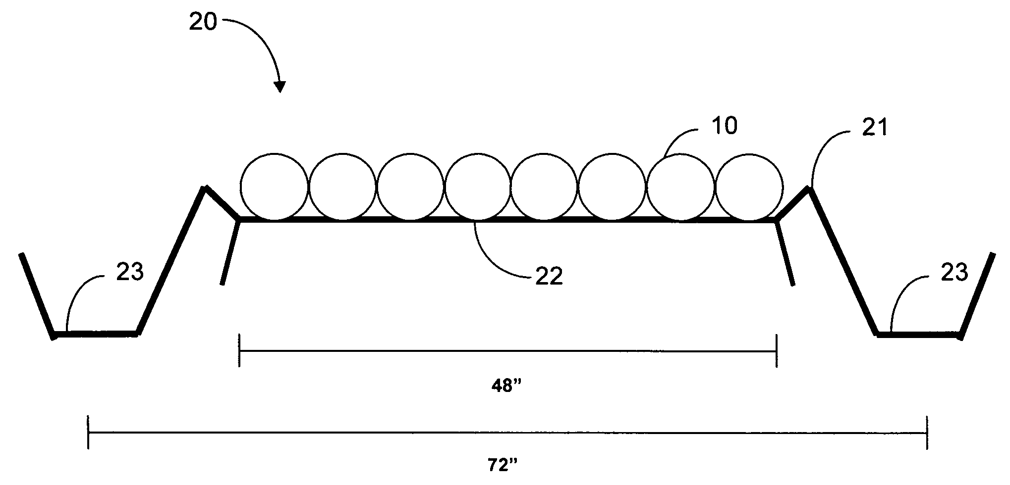
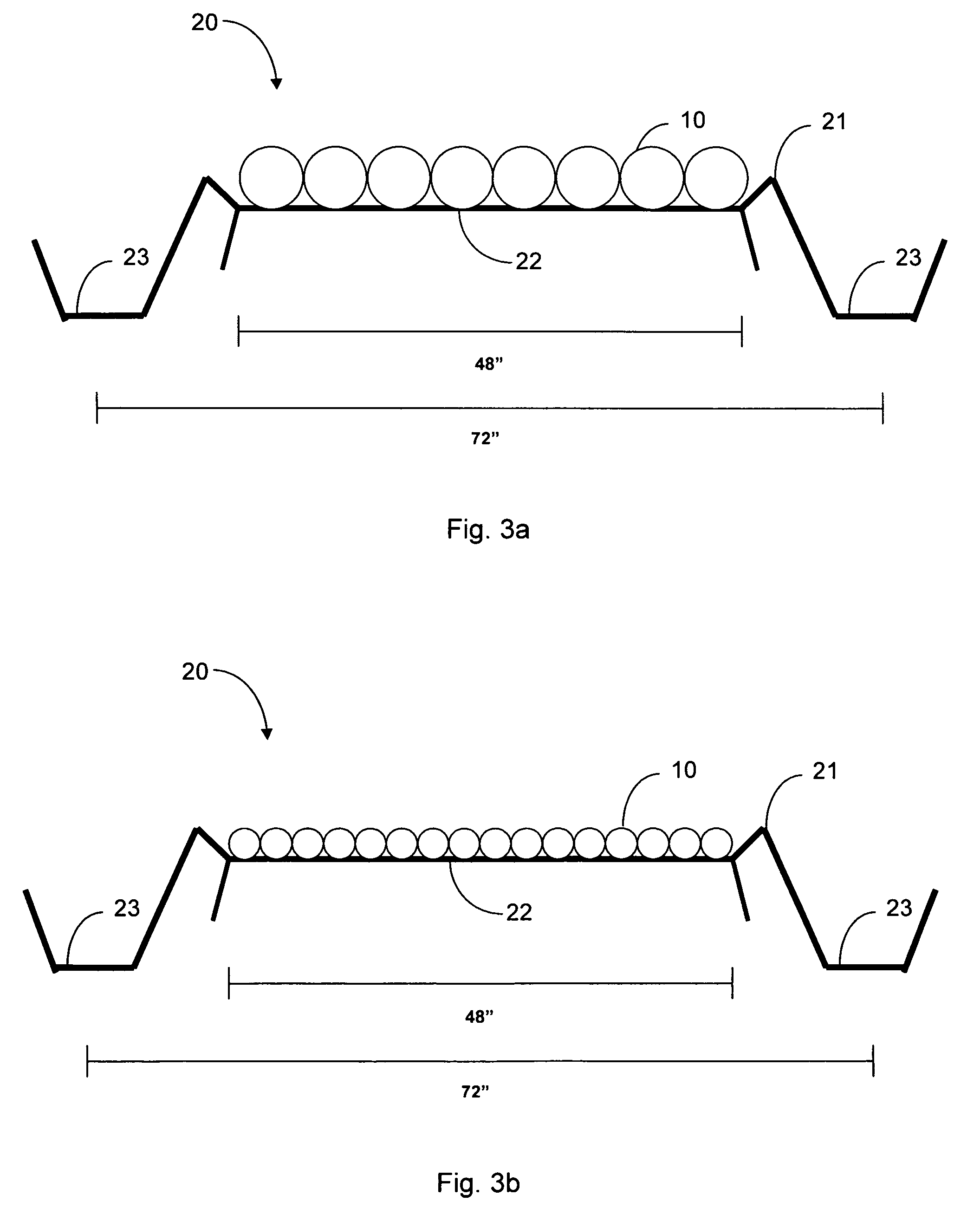
[0043]The preferred embodiment comprises the second embodiment as shown in FIG. 8: a single field 35 of 40 gross acres (1320 ft×1320 ft); 33 net acres of reactor beds 20 (1200 ft×1250 ft); 22 net acres of reactor area (792 ft×1250 ft); a flow rate of 700 gpm / field or 3.5 gpm / bed or 0.22 gpm / line; and algae dwell time of 3.5 hours.

[0044]The pressurized bioreactor system is scalable. For large scale algae production, a series of reactor fields will be interconnected into a common algae collection point for ease of processing. A reactor field is a series of reactor beds 20 that are supplied by a single inlet valve, circulation pump, CO2 injection system, air relief valves, and outlet valve. Most of the components may be adapted from common components currently produced and used in drip irrigation systems. These components include low-cost, thin-wall, durable tubing, water and air-relief valves, pvc pipe, mechanical pumps and filters. Each reactor field is designed to provide an adequat...


PUM


Abstract

An apparatus for producing algae circulates algae fluid through flexible reactor tubing that is at least partially translucent to sunlight. The reactor tubing lies flat when not pressurized. Preferably, the reactor tubing is made of clear polyethylene with UV inhibitors, the polyethylene being between 6 and 15 mil thick. The reactor tubing preferably has a substantially circular cross-section with a 6 inch diameter and is preferably 1250 feet long. Gas relief valves allow gases generated during algae production to escape from the reactor tubing. CO2 may be injected into the algae fluid to stimulate photosynthesis. A circulation pump propels the algae fluid through the reactor tubing, keeping the reactor tubing pressurized and stationary without touching the reactor tubing, so that a rigid support structure is not needed. One or more layers of plastic mulch may be disposed above or below the reactor tubing to control temperature and sunlight exposure.

Description

CROSS-REFERENCE TO RELATED APPLICATIONS[0001]This application claims the benefit of co-pending provisional application No. 60 / 932,674, filed May 31, 2007.FIELD OF INVENTION[0002]This invention relates to algae production systems. This invention relates particularly to a pressurized system of flexible tubing for producing algae.BACKGROUND[0003]Microscopic algae are unicellular organisms which produce oxygen by photosynthesis. Microscopic algae, referred to herein as algae, include flagellates, diatoms and blue-green algae; over 100,000 species are known. Algae are used for a wide variety of purposes, including the production of vitamins, pharmaceuticals, and natural dyes; as a source of fatty acids, proteins and other biochemicals in health food products; for biological control of agricultural pests; as soil conditioners and biofertilizers in agriculture; the production of oxygen and removal of nitrogen, phosphorus and toxic substances in sewage treatment; in biodegradation of plasti...

Claims


Application Information

Patent Timeline
IPC IPC(8): C12M1/02C12M1/08C12R1/89
CPCC12M21/02C12M23/06C12M23/26C12M23/58C12M39/00C12N1/12
Inventor CLOUD, GEORGE BENJAMINNARADIKIAN, SOURENIRWIN, STEPHEN
Owner XL RENEWABLES
Why Eureka
Try Eureka