Calibrating Method of Current Detection Type Thermocouple or the Like, Calibration Method of Offset of Operational Amplifier, Current Detection Type Thermocouple, Infrared Sensor and Infrared Detector

a current detection type, thermocouple technology, applied in the direction of instruments, heat measurement, calorimeters, etc., can solve the problems of inability to establish calibration methods for precisely detecting temperature changes, extreme internal resistance of thermopiles, etc., to achieve easy calibration, large temperature difference tr, and high precision

Inactive Publication Date: 2008-12-25
KIMURA GIKEN KK
View PDF0 Cites 55 Cited by
  • Summary
  • Abstract
  • Description
  • Claims
  • Application Information

AI Technical Summary

Benefits of technology

[0058]In the method for calibrating a current detection type thermocouple according to an aspect of the present invention, a calibrating thermocouple is provided, and a large temperature difference ΔTr can be generated to the calibrating thermocouple using a heating unit. Therefore, an absolute thermoelectric power Ero of the calibrating thermocouple can be obtained easily. Because the detecting thermocouple can be manufactured in the same conditions as the calibrating thermocouple, the detecting thermocouple can be calibrated easily at a high precision.
[0059]In the method for calibrating a current detection type thermocouple according to another aspect of the present invention, the calibrating thermocouple and the detecting thermocouple can be formed as thin film thermocouples on the same substrate, and can be arranged near to each other. Therefore, the calibration precision can be advantageously improved.
[0060]In the method for calibrating a current detection type thermocouple according to still another aspect of the present invention, a heater using Joule heat is used as the heating unit to heat a part of the substrate and to generate the temperature difference ΔTr. Therefore, an easy-to-use calibration method can be provided.
[0061]In the method for calibrating a current detection type thermocouple according to still another aspect of the present invention, a temperature difference ΔTr between two junctions (a hot junction and a cold junction) of the calibrating thermocouple is measured with a pair of temperature sensors provided on the same substrate where the calibrating thermocouple is provided. Therefore, a highly precise calibration can be advantageously performed easily.
[0062]In the method for calibrating a current detection type thermocouple according to still another aspect of the present invention, a semiconductor, added with an impurity in a density high enough to degenerate so as to be reduced in a resistance, is used as one of conductors provided to the thermocouple. If this arrangement is used, the thermoelectromotive force generally becomes lower than that in a semiconductor with a high resistance. While the thermoelectromotive force is just a fraction, the resistance can be reduced, for example, by four digits. Therefore, a highly sensitive temperature sensor can be provided. In addition, the semiconductor with a reduced resistance generally has a larger internal resistance than that of a metal. Because a metal wire has a low resistance, it is possible to handle the internal resistance of the thermocouple as a fraction of the reduced resistance of the semiconductor (10 ohms at most). Therefore, because this fraction of the resistance is low, even if the metal wire is used, the resistance of the wires can be advantageously ignored in calibration. Furthermore, upon detecting a current variation using the operational amplifier (OP Amp), an input resistance to the operational amplifier cannot be brought down too low. From this view point, it is also advantageous to use the semiconductor with the resistance thereof reduced.
[0063]In the method for calibrating a current detection type thermocouple according to still another aspect of the present invention, the calibration can be performed easily, even if one of the junctions (for example, the hot junction) is formed on a cantilever, a micro-air-bridge, or a diaphragm that is a thin film thermally separated from the substrate (for example, a thin film floating in midair).

Problems solved by technology

However, if a semiconductor whose resistivity is too high is used, the thermopile would end up having an extremely high internal resistance.
No established calibration method has been available for detecting a temperature change precisely, with the thermocouple having a hot junction on a cantilever, a micro-air-bridge, or a diaphragm.
However, because almost a hundred of extremely thin thermocouples (2 micrometers or so) are serially connected, the internal resistance of the thermopile becomes extremely high, resulting in lower S / N and lower sensitivity.
However, the larger the number of the thermocouples is, the more the operational amplifiers are required.

Method used


Image

  • Calibrating Method of Current Detection Type Thermocouple or the Like, Calibration Method of Offset of Operational Amplifier, Current Detection Type Thermocouple, Infrared Sensor and Infrared Detector
  • Calibrating Method of Current Detection Type Thermocouple or the Like, Calibration Method of Offset of Operational Amplifier, Current Detection Type Thermocouple, Infrared Sensor and Infrared Detector
  • Calibrating Method of Current Detection Type Thermocouple or the Like, Calibration Method of Offset of Operational Amplifier, Current Detection Type Thermocouple, Infrared Sensor and Infrared Detector

Examples


first embodiment

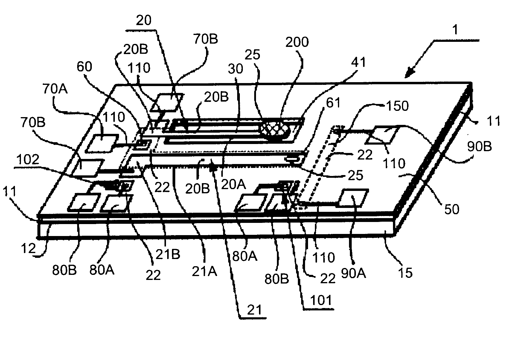
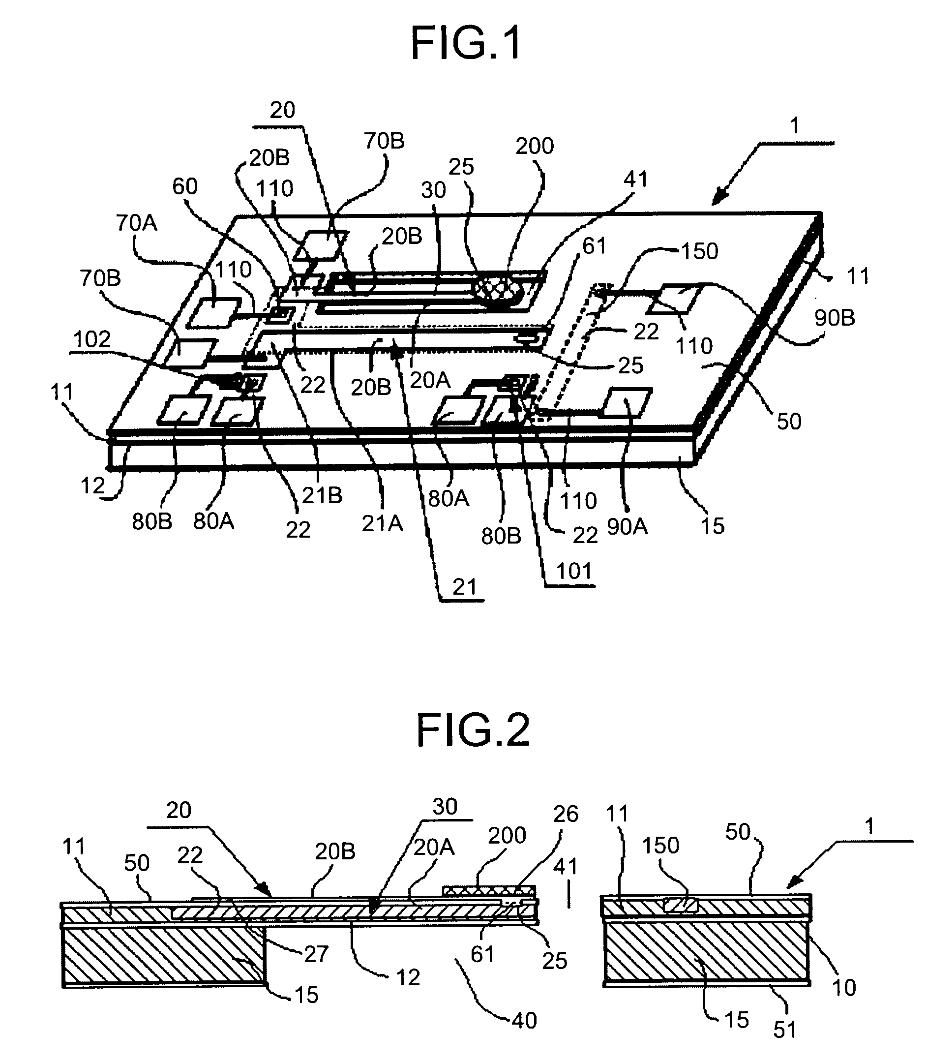
[0135]FIG. 1 is a schematic perspective view of an example of a sensor chip 1 provided onto a current detection type thermocouple, explaining the current detection type thermocouple and a calibration method thereof according to an embodiment of the present invention. In this embodiment, the sensor chip 1 is implemented as a thermal infrared sensor using a detecting thermocouple 20. The sensor chip 1 is provided onto a calibrating thermocouple 21, a pair of calibrating temperature sensors 101, 102, and a self-heating heater 150. In this embodiment, a substrate 10 (SOI substrate) having a p-type SOI layer 11 is used to form an n-type diffusing area 22, by adding a n-type impurity, such as phosphorus, onto the SOI layer 11 in a high density just enough to degenerate. This n-type diffusing area 22 is used as one of conductors, a conductor 20A, of the detecting thermocouple 20 and the calibrating thermocouple 21. The other conductor 20B is made of nickel (Ni), for example, and the detect...

second embodiment

[0143]FIG. 5 is a schematic perspective view of another example of the sensor chip 1 provided with a current detection type thermocouple, explaining the current detection type thermocouple and a calibration method thereof according to an embodiment of the present invention. FIG. 5 is basically same as FIG. 1 mentioned above. However, FIG. 5 is different from FIG. 1 in that a thermocouple including different conductors 120A, 120B is used as the temperature sensor 101 for detecting the temperature difference in the calibrating thermocouple 21. This thermocouple may be manufactured, for example, using gold (Au) and nickel (Ni) for each of the conductor 120A and 120B.

third embodiment

[0144]In this embodiment, instead of the heater 150 formed on the substrate in the first and the second embodiments (shown in FIG. 1 and FIG. 5, respectively), the heater 150, not shown, is manufactured separately and brought near or in contact with the substrate. In this manner, the detecting thermocouple 20 is calibrated using the calibrating thermocouple 21 and a pair of the temperature sensors 101, 102 (using only the temperature sensor 101 in some situations), and following the method described above.


PUM

PropertyMeasurementUnit
resistivityaaaaaaaaaa
ON resistanceaaaaaaaaaa
temperatureaaaaaaaaaa

Abstract

To calibrate a thermocouple, a calibrating thermocouple, made of the same thermocouple material as a detecting thermocouple, is used. An absolute thermoelectric power Ero, of the calibrating thermocouple is determined in advance, and the detecting thermocouple is assumed to have the same Ero. An internal resistance rs of the detecting thermocouple is obtained, and a short-circuit current Is is measured with a measured temperature difference ΔTs using an operational amplifier, and the temperature difference ΔTs is calculated. An offset of the operational amplifier is also calibrated. The thermocouples and switches are connected to an inverting input terminal of the operational amplifier, so that the sensors can be selected. Alternatively, these are connected to a non-inverting input terminal, allowing a plurality of the thermocouples to be switched, while a small resistor r is connected to the inverting terminal thereof, to provide an equivalent current detection type thermocouple. In this manner, even if a hot junction or a cold junction is formed on a cantilever or a diaphragm, the temperature can be calibrated or corrected easily at a high precision.

Description

TECHNICAL FIELD[0001]The present invention relates to a method for calibrating a so-called current detection type thermocouple that obtains a temperature difference to be detected upon detecting a temperature difference using a thermocouple, based a current flowing through a closed circuit including the thermocouple, not based on an open-circuit voltage of its thermoelectromotive force. Furthermore, the present invention relates to a method for calibrating an offset in an operational amplifier that is used for measuring a short-circuit current of the current detection type thermocouple. Still furthermore, the present invention relates to a current detection type thermocouple, an equivalent current detection type thermocouple, and an infrared sensor, and an infrared detecting apparatus applied with the foregoing.BACKGROUND ART[0002]Conventionally, to detect a temperature difference, two junctions, a hot junction and a cold junction, of a thermocouple are arranged at locations having ...

Claims


Application Information

Patent Timeline
Patent Type & Authority Applications(United States)
IPC IPC(8): G01K15/00G01K7/02
CPCG01J5/16G01K7/02G01K15/00G01K15/005
Inventor KIMURA, MITSUTERU
Owner KIMURA GIKEN KK
Why Eureka
Try Eureka