
Nonlinear Chirped Pulse Fiber Amplifier With Pulse Compression

a fiber amplifier and chirped pulse technology, applied in the direction of fiber transmission, laser details, electrical equipment, etc., can solve the problems gain bandwidth modification, and distortion of pulse spectral and temporal profiles, so as to achieve the cleanest shape, increase the amount of nonlinear phase shift, and increase the gain of the fiber amplifier

Inactive Publication Date: 2009-01-01
CORNELL UNIVERSITY
View PDF20 Cites 12 Cited by
  • Summary
  • Abstract
  • Description
  • Claims
  • Application Information

AI Technical Summary

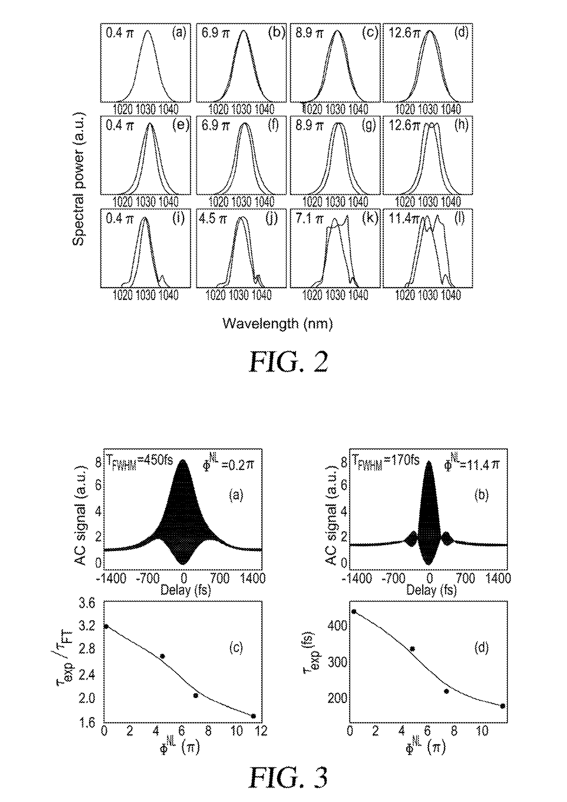
Benefits of technology

[0012]The discovery of the unexpected behavior of the CPA system disclosed in Wise et al. has led to yet another unexpected way in which effects that were previously thought to be detrimental to performance of a CPA fiber system can in fact be combined to generate even higher energy, ultrashort pulses using an all fiber system. In particular, the inventors have now discovered that shaping (i.e. broadening) of the power spectrum of a pulse in an amplifier (which arises from nonlinear phase shifts as high as 12π or more) can be exploited to reduce the pulse duration proportionally. A shorter pulse duration is generally desirable, for better temporal resolution in measurements, or to create higher peak power with fixed pulse energy.
[0015]In operation, the design of the three stages is such that the large nonlinear phase shifts accumulated by the pulse in the amplifier compensate the mismatch of dispersions of the fiber stretcher and grating compressor. The amount of nonlinear phase shift is preferably increased by increasing the gain in the fiber amplifier, which results in spectral broadening of the pulse. For given parameters of the stretcher, amplifier and compressor, an optimal value of the nonlinear phase shift can be identified, at which value the output pulse has the shortest duration, cleanest shape and highest peak power. The result is a fiber amplifier that, contrary to previous reports, can perform optimally and actually improves with large values of nonlinearity and resultant spectral broadening. The pulses generated using this technique can actually be shorter than the gain narrowing limit of the fiber amplifier. In the case of a ytterbium fiber amplifier, which has a gain narrowing limit of 120 femtoseconds, experiments using the technique of the subject invention have demonstrated generation of pulses of substantially less than 120 femtoseconds and even less than 100 femtoseconds.

Problems solved by technology

Gain narrowing leads to distortion of the pulse spectral and temporal profiles.
Among fiber devices, gain spectrum or bandwidth limitations have been considered in the context of self-similar amplification, but there has been no known treatment of this issue in fiber CPA.
Wise et al. demonstrated that ΦNL of π or greater can be employed in a CPA system, though it was still presumed that any gain bandwidth modifications either could not be induced or would be detrimental if they were induced.

Method used


Image

  • Nonlinear Chirped Pulse Fiber Amplifier With Pulse Compression
  • Nonlinear Chirped Pulse Fiber Amplifier With Pulse Compression
  • Nonlinear Chirped Pulse Fiber Amplifier With Pulse Compression

Examples


Embodiment Construction

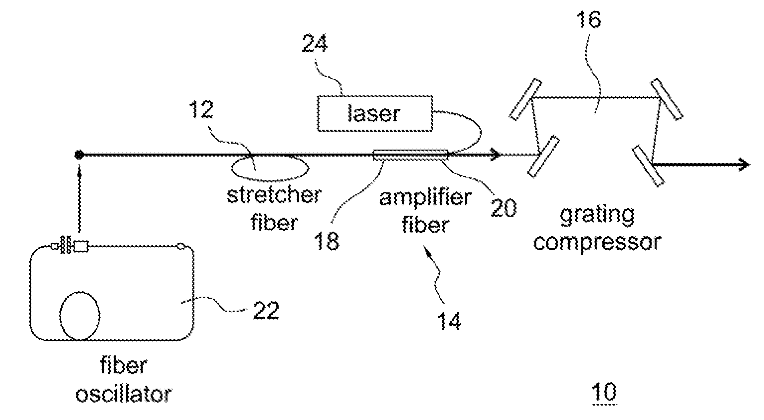
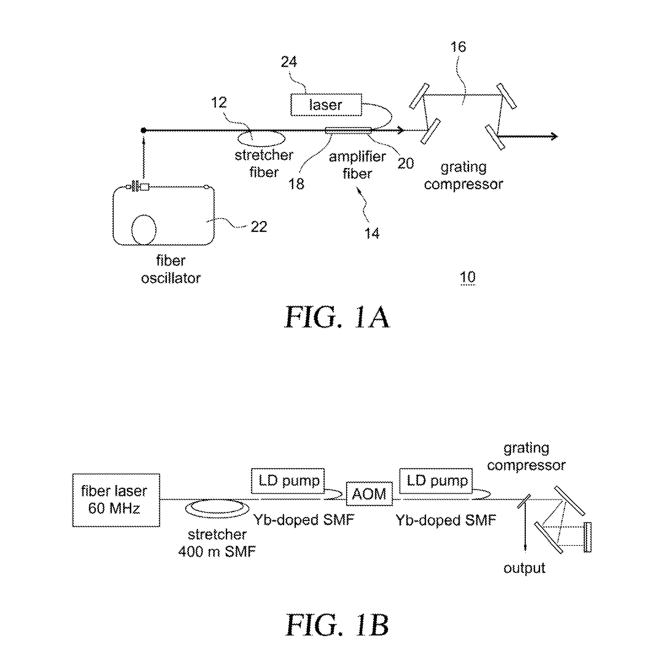
[0021]A chirped-pulse amplifier system 10 for generating high energy femtosecond-duration optical pulses that is constructed in accordance with a preferred embodiment of the present invention is illustrated in FIG. 1A. The CPA system 10 consists of three stages: a pulse stretcher 12, an amplifier 14 and a compressor 16. The stretcher 12 preferably consists of a segment of single-mode optical fiber (SMF). The amplifier 14 is also preferably implemented with fiber, at least a first section 18 of which is doped with an element that provides the gain, such as ytterbium or erbium. A second optional section 20 of undoped single mode fiber is preferably included, which can be used to add a selectable amount of nonlinear phase shift to the system 10 for reasons to be discussed shortly. The compressor 16 is a dispersive delay line which will most commonly be implemented with a pair of diffraction gratings. It should be understood that other types of elements could be used for the pulse stret...


PUM


Abstract

A chirped-pulse fiber amplification method and system operates with large nonlinear phase shifts (as large as ˜20π or more). In this regime, the pulse spectrum is modified by strong self-phase modulation and gain shaping. With large-enough nonlinear phase shift, substantial spectral broadening occurs. The amplified spectrum can therefore be much broader than the spectrum that is obtained with small nonlinear phase shifts. The broader spectrum enables the formation of a shorter pulse, and the bandwidth generated in nonlinear chirped-pulse amplification can in fact be exploited to generate shorter pulses. Ultimately, this allows the generation of pulses shorter than the gain-narrowing limit of a fiber amplifier.

Description

CROSS REFERENCE TO RELATED APPLICATIONS[0001]This application claims the benefit, under 35 U.S.C. 119(e), of U.S. Provisional Application No. 60 / 940,076, filed May 25, 2007, which is hereby incorporated by reference in its entirety.GOVERNMENT SPONSORSHIP STATEMENT[0002]This invention was made with Government support from the National Science Foundation under Contract No. ESC-0500596. The Government has certain rights in the invention.BACKGROUND OF THE INVENTION[0003]1. Field of the Invention[0004]The present invention relates, in general, to short-pulse fiber amplifiers, and more particularly to a chirped pulse fiber amplifier which exploits large nonlinear phase shifts to produce shorter pulses. This avoids the pulse-broadening that generally occurs owing to the gain bandwidth of the amplifier.[0005]2. Description of the Background Art[0006]There is rapidly growing interest in the development of efficient, compact, and stable ultrafast lasers for a variety of applications from the ...

Claims


Application Information

Patent Timeline
IPC IPC(8): H01S3/00H04B10/12
CPCH01S3/0057H01S3/06725H04B10/508H01S3/1618H04B10/291H01S3/06754
Inventor WISE, FRANK W.KUZNETSOVA, LYUBACHONG, CHIN YU
Owner CORNELL UNIVERSITY
Learn More